


As AI processors become more powerful, thermal management is becoming increasingly dependent on the geometry of the heat dissipation system.
A heat sink may look relatively simple, but its performance depends on many interacting variables:
- Fin height
- Fin thickness
- Fin spacing
- Fin density
- Fin length
- Base thickness
- Airflow direction
- Cooling medium
- Manufacturing process
For high-density AI systems, simply adding more aluminum heat sink fins does not necessarily produce better cooling.
A higher fin density can increase surface area, but it can also restrict airflow and increase pressure drop.
The real engineering challenge is to find the right balance between:
Surface Area + Airflow + Thermal Resistance + Structural Strength + Manufacturability
This is the foundation of effective AI heat sink fin design.
1. Why Fin Geometry Matters in AI Cooling
The basic purpose of a heat sink is to move heat from a high-temperature component into a larger surface area where it can be transferred to the surrounding cooling medium.
A simplified thermal path is:
GPU / Processor
→ Thermal Interface
→ Heat Sink Base
→ Fins
→ Air or Other Cooling Medium
Every part of this path contributes to the final thermal performance.
The fin structure is particularly important because it determines:
- Available heat-transfer area
- Airflow resistance
- Temperature distribution
- Weight
- Manufacturing complexity
For high-power AI processors, small changes in geometry can therefore have meaningful system-level consequences.
2. What Makes AI Heat Sink Design Different?
Conventional electronics cooling often deals with relatively moderate heat loads.
AI accelerators can generate much higher heat fluxes while occupying a compact physical area.
This creates several challenges:
- High local heat generation
- Limited installation space
- High component density
- Restricted airflow paths
- Greater thermal interface sensitivity
The heat sink therefore needs to move heat efficiently without creating an excessive airflow penalty.
This makes high-density thermal management a multi-variable optimization problem.
3. Fin Density: More Is Not Always Better
Fin density refers to how closely the fins are spaced.
Increasing fin density generally increases the available surface area within a given footprint.
However, there is a trade-off.
Lower Fin Density
Potential advantages:
- Lower airflow resistance
- Easier cleaning
- Easier extrusion
- Better airflow penetration
Potential disadvantages:
- Lower surface area
- Larger required heat sink footprint
Higher Fin Density
Potential advantages:
- Greater surface area
- More compact thermal structure
Potential disadvantages:
- Higher airflow resistance
- More difficult manufacturing
- Greater risk of airflow bypass or non-uniform distribution
Therefore, the optimum fin density depends on the cooling system.
4. Surface Area vs Airflow Resistance
This is one of the central relationships in AI heat sink fin design.
Adding fins increases surface area.
But adding more fins also narrows the air passages.
As the passages become smaller, airflow resistance can increase.
The simplified relationship is:
More Fins
→ More Surface Area
but potentially:
More Fins
→ Higher Pressure Drop
The best design is therefore not the heat sink with the maximum number of fins.
It is the heat sink that provides the required thermal performance within the available airflow budget.
5. Fin Spacing
Fin spacing determines how easily the cooling medium can pass through the heat sink.
If spacing is too large:
- Surface area may be underutilized.
- The heat sink may become unnecessarily large.
If spacing is too small:
- Airflow resistance increases.
- Dust accumulation may become more significant.
- Manufacturing becomes more difficult.
- Actual airflow through the fins may become less uniform.
The correct spacing depends on:
- Fan capability
- Airflow velocity
- Heat load
- Fin height
- Fin thickness
- Operating environment
6. Fin Height
Increasing fin height generally increases surface area.
However, taller fins can also introduce:
- Higher airflow resistance
- Greater structural flexibility
- More difficult extrusion
- Temperature gradients along the fin
A very tall fin may not perform as expected if airflow cannot effectively reach its entire surface.
For this reason, fin height should be evaluated together with airflow conditions rather than considered independently.
7. Fin Thickness
Fin thickness affects both thermal and mechanical behavior.
Thinner fins can provide:
- Higher fin density
- More surface area within a fixed footprint
- Lower material usage
But very thin fins can create:
- Manufacturing limitations
- Lower mechanical stiffness
- Greater sensitivity to deformation
- More difficult handling
For extruded aluminum heat sinks, fin thickness is also influenced by:
- Alloy
- Extrusion ratio
- Profile geometry
- Fin height
- Die design
Theoretical optimization therefore needs to remain compatible with the actual manufacturing process.
8. Fin Length and Airflow Direction
Fin geometry should be designed around the actual airflow direction.
For example, if air enters from one side and exits from the opposite side, the fin arrangement should provide a relatively consistent flow path.
Potential problems occur when:
- Air enters at an angle.
- The heat sink is partially blocked.
- Adjacent components restrict the inlet.
- Cable bundles obstruct airflow.
A heat sink should therefore be evaluated as part of the complete server airflow architecture.
9. Heat Sink Base Thickness
The base connects the heat source to the fin structure.
A base that is too thin may create:
- Excessive temperature gradients
- Local deformation
- Poor mechanical stability
A base that is unnecessarily thick adds:
- Weight
- Material
- Thermal mass
The base must provide sufficient heat spreading while maintaining an efficient thermal path.
For high-power GPU cooling, local heat concentration should be considered carefully.
10. Heat Spreading Before the Fins
A heat sink does not automatically distribute heat uniformly across its entire fin field.
If the heat source is highly concentrated, the base may need to spread the heat before it reaches the fins.
The thermal path becomes:
GPU Hot Spot
→ TIM
→ Base Plate
→ Heat Spreading
→ Fin Array
→ Airflow
This is why base thickness, material conductivity, and heat source geometry are important.
A fin array can only perform effectively if heat reaches the fins efficiently.
11. Aluminum as a Heat Sink Material
Aluminum is widely used for heat sinks because it offers a useful combination of:
- Thermal conductivity
- Low density
- Corrosion resistance
- Extrudability
- Machinability
- Recyclability
For AI infrastructure, this combination is particularly valuable because thermal components can become large and mechanically integrated.
Aluminum allows engineers to create lightweight fin structures without adding unnecessary mass to the server or rack.
12. Extruded Aluminum Heat Sink Fins
Extrusion is one of the most practical ways to manufacture repeated aluminum fin geometries.
A customized extrusion die can produce:
- Base plate
- Fin array
- Mounting channels
- Structural ribs
in one continuous profile.
This creates a significant manufacturing advantage.
Instead of machining every fin individually, the fin geometry is formed during extrusion.
This is particularly attractive for medium- to high-volume applications with relatively stable designs.
13. Extrusion Limitations
Extrusion does not mean unlimited geometric freedom.
Fin design is constrained by:
- Fin height
- Fin thickness
- Spacing
- Profile width
- Wall thickness
- Alloy
- Extrusion ratio
- Die complexity
Very thin, very tall, closely spaced fins may be difficult or expensive to extrude reliably.
Therefore:
Thermal Optimization
must always be followed by:
Extrusion Feasibility
A theoretically excellent heat sink is not necessarily a commercially useful design if it is difficult to manufacture consistently.
14. Extrusion vs CNC Machining
Different heat sink geometries favor different manufacturing methods.
Extrusion
Best suited to:
- Repeated fin geometry
- Long profiles
- Medium/high production volumes
- Integrated mounting features
CNC Machining
Useful for:
- Complex local geometries
- Precision mounting surfaces
- Port features
- Small production quantities
- Prototypes
Hybrid Manufacturing
Often provides the best balance:
Extruded Fin Profile
CNC-Machined Base
Precision Mounting Features
This approach can reduce machining time while maintaining dimensional accuracy where needed.
15. Folded and Bonded Fin Structures
For applications requiring extremely high fin density, other manufacturing approaches may be considered.
These can include:
- Folded fins
- Bonded fins
- Skived fins
They may provide different combinations of:
- Fin density
- Surface area
- Thermal performance
- Manufacturing complexity
However, the appropriate technology depends on:
- Heat load
- Space
- Airflow
- Production volume
- Cost
- Required geometry
There is no universal heat sink manufacturing process for every AI application.
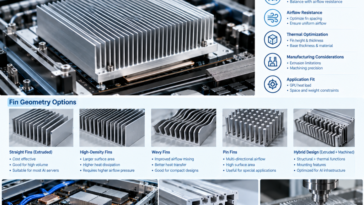
16. Pin Fin vs Straight Fin Geometry
Two common concepts are straight-fin and pin-fin structures.
Straight Fins
Provide relatively predictable airflow paths.
Potential advantages:
- Simple geometry
- Good extrusion compatibility
- Easy cleaning
- Efficient for directional airflow
Pin Fins
Provide multidirectional airflow interaction.
Potential advantages:
- Useful where airflow direction is less uniform
- Can provide high surface area
However, pin-fin structures may be more difficult to manufacture using conventional extrusion.
The choice should therefore consider both thermal performance and manufacturing method.
17. Airflow Distribution Across High-Density Heat Sinks
One of the most important considerations is whether airflow actually reaches the entire fin array.
A high-density heat sink can theoretically provide large surface area.
But if airflow bypasses part of the structure, the effective thermal performance may be lower than expected.
Potential causes include:
- Uneven fan distribution
- Adjacent components
- Gaps around the heat sink
- Poor duct design
- Cable obstruction
Therefore, heat sink design should be coordinated with airflow management.
18. Heat Sink Fin Design for GPU Servers
GPU systems can generate concentrated heat over relatively compact areas.
This makes the interface between the GPU and heat sink particularly important.
Engineers should consider:
- GPU package dimensions
- Hot spot distribution
- TIM thickness
- Mounting pressure
- Base flatness
- Fin orientation
- Airflow direction
The heat sink should be designed around the actual GPU thermal map rather than only the nominal power rating.
19. Thermal Interface Resistance
The heat sink is only one part of the thermal path.
The interface between the processor and heat sink can contribute significant thermal resistance.
Potential factors include:
- TIM thickness
- Surface flatness
- Contact pressure
- Surface roughness
- Assembly tolerances
The simplified thermal chain is:
GPU
→ TIM
→ Aluminum Base
→ Fins
→ Air
Optimizing the fin array while neglecting the thermal interface can produce limited system-level improvement.
20. Fin Orientation in AI Infrastructure
Fin direction should generally follow the intended cooling airflow.
For a conventional front-to-back server architecture, fins may be aligned with the primary airflow path.
However, AI infrastructure may also use:
- Side-to-side airflow
- Top-to-bottom airflow
- Hybrid airflow
- Ducted cooling
Therefore, fin orientation should be selected based on the actual system.
21. Passive vs Forced-Air Heat Sink Design
AI systems may use either passive or forced-air cooling for specific components.
Passive Cooling
Depends primarily on:
- Natural convection
- Surface area
- Thermal conduction
This usually requires larger surface area and favorable geometry.
Forced-Air Cooling
Uses fans or blowers to increase heat transfer.
This allows greater heat rejection from a smaller structure but introduces:
- Pressure drop
- Fan power
- Noise
- Airflow management requirements
For high-density AI servers, forced airflow is often an important part of the thermal architecture.
22. Fin Geometry and Fan Selection
Heat sink and fan design should not be separated.
A heat sink creates resistance to airflow.
The fan provides pressure and flow.
The operating point is determined by the interaction between:
Fan Curve
and
System Pressure Drop
A heat sink with extremely dense fins may require a fan capable of generating higher static pressure.
If the fan cannot provide that pressure, actual airflow may be lower than expected.
Therefore:
Heat Sink + Fan + Duct = One Thermal System
23. Dust and Environmental Exposure
Fin spacing also matters in real operating environments.
High-density fins can collect:
- Dust
- Fibers
- Particles
Over time, accumulation can reduce effective airflow.
This is especially important for:
- Edge AI
- Outdoor enclosures
- Industrial computing
- Distributed AI systems
A slightly lower theoretical surface area may sometimes provide better lifecycle performance if it allows easier cleaning and more stable airflow.
24. Surface Treatment of Aluminum Heat Sinks
Aluminum heat sinks may use surface treatments for:
- Corrosion protection
- Appearance
- Wear resistance
- Electrical requirements
Possible treatments include:
- Anodizing
- Conversion coatings
- Protective coatings
The treatment should be selected based on the actual application.
Surface treatment can also influence:
- Surface emissivity
- Electrical conductivity
- Dimensional tolerance
Therefore, thermal and electrical requirements should be considered together.
25. Structural Function of Heat Sink Fins
Fins are primarily thermal structures, but they can also contribute to mechanical stiffness.
A properly designed fin array may help resist:
- Local deformation
- Vibration
- Handling loads
However, fins should not automatically be treated as primary structural members.
The mechanical load path should be deliberately designed.
For AI infrastructure, this distinction is important when the heat sink is integrated into a server chassis or aluminum structural frame.
26. Integrating Heat Sinks With Aluminum Structures
A more advanced design may combine:
Heat Sink
Structural Frame
Mounting Interface
into one aluminum component.
For example, an aluminum extrusion could contain:
- External cooling fins
- Internal structural ribs
- Mounting channels
- Cable-routing features
This can reduce component count and simplify assembly.
However, thermal performance and structural requirements must be evaluated together.
27. Fin Density and Manufacturing Cost
Fin density also affects manufacturing economics.
Higher fin density may require:
- More complex extrusion dies
- Tighter process control
- More difficult finishing
- More demanding inspection
For CNC-machined structures, higher fin density can increase:
- Machining time
- Tool wear
- Programming complexity
Therefore, the best design is not necessarily the one with the highest thermal performance in isolation.
It should deliver the required performance at a practical production cost.
28. Designing for Production Volume
The optimal manufacturing process depends heavily on volume.
Prototype
CNC machining may be appropriate because tooling investment is limited.
Small Batch
Hybrid extrusion + CNC can provide flexibility.
Medium Production
Customized extrusion can reduce per-unit machining.
High Volume
A highly optimized extrusion profile may provide significant manufacturing advantages.
This is why manufacturing strategy should be considered during thermal design.
29. Thermal Simulation for Fin Optimization
Thermal simulation can help evaluate different fin configurations before physical prototypes are manufactured.
Variables may include:
- Fin height
- Fin thickness
- Fin spacing
- Base thickness
- Air velocity
- Heat load
The objective is not simply to maximize surface area.
The engineer may instead optimize:
Thermal Resistance
subject to:
- Maximum pressure drop
- Maximum dimensions
- Manufacturing constraints
- Weight limits
Simulation can significantly reduce the number of physical iterations required.
30. Experimental Validation
Simulation should be supported by physical testing.
A prototype heat sink can be evaluated for:
- Thermal resistance
- Temperature distribution
- Airflow
- Pressure drop
- Fan operating point
A useful development process is:
Simulation
→ Prototype
→ Thermal Test
→ Compare With Model
→ Geometry Optimization
→ Production Validation
This helps identify differences between theoretical and real-world performance.
31. Common Heat Sink Fin Design Mistakes
Mistake 1: Maximizing Fin Density
More fins can increase pressure drop.
Mistake 2: Ignoring Airflow Direction
A fin array must work with the actual cooling architecture.
Mistake 3: Making Fins Too Tall
Very tall fins may increase manufacturing difficulty and airflow resistance.
Mistake 4: Ignoring the Thermal Interface
A highly optimized fin structure cannot compensate for excessive TIM resistance.
Mistake 5: Designing Without Manufacturing Constraints
An ideal geometry may not be practical to extrude or machine.
Mistake 6: Ignoring Dust Accumulation
High-density fin arrays can be sensitive to contamination.
Mistake 7: Optimizing Thermal Performance Only
Weight, cost, structural strength, serviceability, and production volume also matter.
32. A Practical AI Heat Sink Fin Design Workflow
A practical engineering process can follow these steps.
Step 1 — Define Heat Load
Identify:
- GPU or processor power
- Hot spot distribution
- Operating temperature
Step 2 — Define Cooling Method
Determine:
- Forced air
- Natural convection
- Hybrid cooling
- Liquid-assisted cooling
Step 3 — Define Space Constraints
Determine:
- Maximum height
- Width
- Length
- Component clearance
Step 4 — Develop Fin Geometry
Optimize:
- Fin height
- Thickness
- Spacing
- Base thickness
Step 5 — Check Airflow
Evaluate:
- Flow rate
- Pressure drop
- Fan capability
Step 6 — Check Manufacturing
Determine:
- Extrusion feasibility
- CNC requirements
- Surface treatment
- Tolerances
Step 7 — Simulate
Perform:
- Thermal analysis
- CFD where appropriate
- Structural analysis
Step 8 — Prototype and Validate
Measure:
- Temperature
- Pressure drop
- Airflow
- Mechanical stability
Step 9 — Optimize for Production
Balance:
Performance + Cost + Manufacturability + Reliability
33. Choosing the Right Fin Geometry for AI Infrastructure
Different AI applications may require different heat sink architectures.
| Application | Potential Fin Strategy | Main Consideration |
|---|---|---|
| GPU server | Dense straight fins | Airflow + heat flux |
| Power electronics | Medium-density fins | Thermal + electrical clearance |
| Edge AI enclosure | Larger-spaced fins | Dust + passive airflow |
| Rack-level cooling | Large structural fins | Strength + thermal performance |
| Compact electronics | High-density fins | Space + pressure drop |
| Outdoor AI equipment | Robust wider fins | Environment + serviceability |
The appropriate geometry depends on the complete system.
34. The Future of Aluminum Heat Sink Design
As AI infrastructure becomes more compact and power-dense, heat sinks are likely to become more integrated with mechanical structures.
Future designs may combine:
- Structural aluminum
- Heat sink fins
- Cooling channels
- Mounting interfaces
- Cable management
- Liquid cooling connections
This creates multifunctional thermal-mechanical components.
Instead of:
Rack + Bracket + Heat Sink + Cooling Support
the architecture may increasingly become:
Integrated Aluminum Thermal-Structural Module
This is particularly relevant to modular AI infrastructure and custom server platforms.
Optimize the Fin System, Not Just the Fin Count
Effective AI heat sink fin design is a balance between thermal performance and practical engineering.
The key variables include:
- Fin density
- Fin spacing
- Fin height
- Fin thickness
- Base thickness
- Airflow direction
- Pressure drop
- Manufacturing process
- Material selection
- Environmental exposure
For aluminum heat sink fins, extrusion offers a powerful manufacturing route for repeated geometries, while CNC machining and hybrid manufacturing provide additional flexibility for precision interfaces and prototypes.
The most effective design is rarely the one with the most fins.
It is the one that achieves the required thermal performance while maintaining:
Efficient Airflow
Adequate Surface Area
Low Thermal Resistance
Manufacturing Feasibility
Mechanical Reliability
Practical Cost
For high-density AI systems, heat sink geometry should therefore be treated as part of the complete thermal architecture.
Heat source → thermal interface → aluminum base → fin geometry → airflow → heat rejection
When these elements are optimized together, aluminum can serve not only as a heat sink material, but as an integrated thermal and structural platform for next-generation AI infrastructure.