

As AI computing systems become more powerful and densely integrated, mechanical hardware must support increasingly demanding requirements. GPU server frames, chassis structures, mounting rails, cooling assemblies, and equipment enclosures must accommodate heavy components while maintaining dimensional stability and reliable operation.
Reducing structural weight can improve handling, simplify installation, and reduce the load imposed on supporting structures. However, lightweight design must not compromise rigidity, mounting accuracy, vibration resistance, or long-term reliability.
For manufacturers developing lightweight aluminum AI server hardware, the objective is not simply to use less aluminum. It is to optimize the relationship between material distribution, structural geometry, applied loads, and manufacturing processes.
This article explains how cross-section optimization, localized reinforcement, hollow-section design, and finite element analysis can help reduce aluminum frame weight while maintaining the required structural performance.
1. Why Weight Reduction Matters in AI Server Hardware
AI server hardware contains multiple mechanical and electronic subsystems, including GPU modules, power supplies, cooling equipment, cable management components, and supporting structures. As these systems become more complex, the mechanical design must balance several competing priorities.
Structural performance
The chassis and supporting frame must carry component loads without excessive deformation. Mounting interfaces must remain sufficiently stable to support reliable assembly and operation.
Installation and handling
Lighter frames and removable structural modules can make transportation, installation, replacement, and maintenance easier. Actual benefits depend on the size of the equipment and the installation procedure.
Space efficiency
A carefully optimized frame can provide the required structural support while preserving room for cooling hardware, cable routing, and component access.
Manufacturing cost
Reducing material volume may lower raw material consumption, but the final cost also depends on tooling, machining time, joining operations, inspection, and production volume.
A lightweight design should therefore be evaluated against the complete manufacturing and operating requirements rather than material weight alone.
2. Start with Load Paths Before Removing Material
One of the most important principles in aluminum frame weight reduction is understanding how loads move through the structure.
A server frame may experience loads from installed components, mounting hardware, transportation, handling, vibration, and installation. These loads do not distribute evenly across every wall or bracket.
Before changing the geometry, engineers should identify:
- The locations where components transfer loads into the frame
- The support points connecting the frame to the rack or enclosure
- The structural members carrying bending, tension, compression, or torsion
- The mounting areas where local deformation could affect alignment
- The joints and fasteners that transfer loads between components
This analysis helps distinguish between material that contributes significantly to structural performance and material that may be reduced or redistributed.
For example, a vertical aluminum rail supporting several heavy modules may require sufficient bending stiffness along its length. A nearby cover panel may primarily provide enclosure or airflow functions and may not require the same structural thickness.
The two components should not be optimized using the same assumptions.
The key principle: Reduce unnecessary material only after understanding its structural function.
3. Optimize Aluminum Extrusion Cross-Sections
Custom aluminum extrusion is an effective manufacturing method for structural members used in AI server frames, mounting rails, and equipment enclosures.
Unlike a simple solid bar, an extrusion can incorporate ribs, channels, cavities, and mounting features into a single cross-section. These features allow engineers to distribute material according to the component’s loading conditions.
Increase structural efficiency through geometry
For bending-dominated structures, material positioned farther from the neutral axis can contribute more to the second moment of area and therefore improve bending stiffness.
This is why a suitably designed hollow profile may provide better stiffness per unit mass than a solid section of comparable material volume.
However, the benefit depends on the bending direction, cross-sectional geometry, wall thickness, and loading conditions.
Integrate mounting features
An optimized profile may combine several functions:
- A primary structural wall
- Internal reinforcing ribs
- T-slots or mounting channels
- Fastener access features
- Cable-routing channels
- Panel-retention interfaces
Integrating these features can reduce the number of separate brackets and fasteners required. It may also simplify assembly and improve repeatability.
However, an overly complicated cross-section can increase extrusion die cost, create manufacturing challenges, or require additional machining. The final design should balance structural performance with extrusion feasibility.
Consider stiffness in multiple directions
A profile optimized for one bending direction may perform poorly in another. AI server frames may experience loads in multiple directions, especially when mounted equipment, access panels, and support members interact.
Engineers should therefore evaluate the principal loading directions and torsional behavior rather than optimizing a single dimension in isolation.
4. Use Hollow Sections Without Creating Weak Points
Hollow aluminum sections can reduce mass while retaining useful structural depth. They are particularly relevant to chassis rails, cross-members, and modular frame components.
Nevertheless, hollow-section design requires more than creating the largest possible internal cavity.
Balance wall thickness and local stability
Thin walls can become susceptible to local deformation or buckling, depending on their unsupported width, material properties, and loading conditions.
An excessively thin wall may also complicate extrusion, machining, fastening, or assembly.
Engineers should evaluate the relationship between wall thickness, unsupported span, rib spacing, and applied load.
Reinforce interfaces selectively
The most demanding areas are often not the middle of a long structural member but the locations where loads enter or leave the structure.
Examples include:
- Screw holes and threaded interfaces
- GPU support brackets
- Rack mounting points
- Corner connections
- Heavy component attachment locations
- Machined pockets near load-bearing regions
A hollow profile may remain lightweight while incorporating thicker material or additional ribs around these critical features.
Avoid cavities that interfere with manufacturing
Internal geometry must remain compatible with the extrusion process. Very thin webs, abrupt thickness transitions, and difficult-to-extrude shapes can affect die complexity and production consistency.
Where complex internal cavities are unnecessary, a simpler profile combined with separate machined brackets may be more economical.
5. Apply Local Reinforcement Instead of Increasing Thickness Everywhere
A common response to structural concerns is to increase wall thickness across the entire component. Although this can increase stiffness and strength, it may add unnecessary weight and material cost.
Localized reinforcement offers a more targeted alternative.
Reinforce high-load regions
Additional material can be placed around mounting points, fastener holes, joints, and concentrated load locations.
Depending on the design, suitable approaches may include thicker local walls, integrated ribs, reinforcement plates, corner brackets, or machined inserts.
Improve load distribution
If a load is concentrated at a small interface, the design may benefit more from a larger contact area or a better-supported connection than from simply increasing the thickness of the entire frame member.
For example, a mounting bracket that distributes component weight across two structural rails may reduce local deformation compared with a bracket that transfers the same load into a single unsupported wall.
Keep reinforcement manufacturable
Reinforcement should be compatible with the selected production process. Integrated extrusion ribs may be suitable for repeated structural features, while CNC-machined reinforcement or separate brackets may be more practical for complex local geometry.
The best option depends on production volume, required tolerances, assembly sequence, and serviceability.
6. Use Finite Element Analysis to Guide Structural Optimization
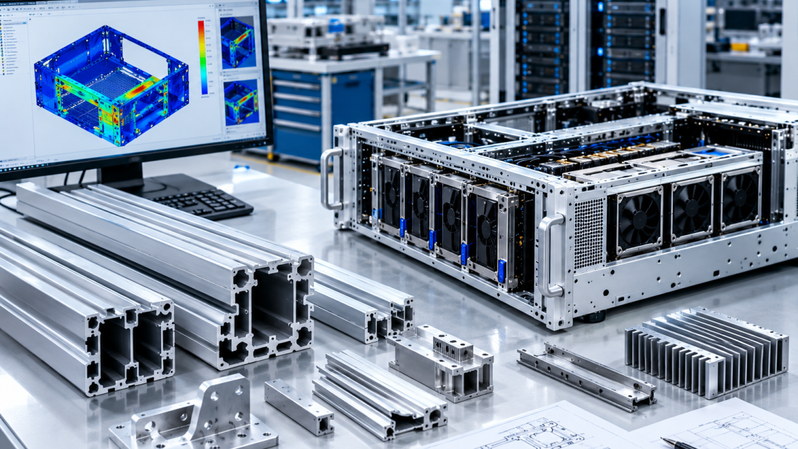
Finite element analysis (FEA) helps engineers understand how a proposed design behaves under defined loading conditions before committing to production tooling.
For lightweight aluminum AI server hardware, FEA can support decisions about material distribution, profile geometry, reinforcement, and mounting arrangements.
Step 1: Define realistic boundary conditions
The model should reflect how the frame is actually supported and loaded. Engineers should include representative component masses, mounting points, fastener constraints, and relevant external loads.
Unrealistic boundary conditions can produce misleading results, even when the simulation itself is numerically well executed.
Step 2: Establish a baseline design
The original or reference geometry provides a starting point for comparison. Record its mass, predicted displacement, stress distribution, and other relevant performance indicators.
Step 3: Identify material that can be optimized
Simulation results may reveal areas with relatively low structural demand and regions where stress or deformation is concentrated.
Low-stress regions may offer opportunities for material reduction, but stress plots alone are not sufficient to justify removing material. Local buckling, fatigue, joint behavior, manufacturing constraints, and the effects of changed load paths must also be considered.
Step 4: Compare design alternatives
Engineers can evaluate alternative wall thicknesses, rib layouts, cavity dimensions, and reinforcement configurations.
A useful comparison should consider both mass and structural performance. For example, two designs with similar stress levels may exhibit different overall displacement or torsional stiffness.
Step 5: Validate the optimized design
FEA results should be checked against physical tests appropriate to the application. Depending on the hardware, these may include static loading, dimensional inspection, vibration testing, or assembly verification.
Simulation is a design tool, not a substitute for defining acceptance criteria and validating the finished product.
7. Understand the Difference Between Strength and Stiffness
A component can have adequate strength and still be too flexible for its intended application.
Strength concerns the ability to withstand applied loads without unacceptable failure or permanent deformation.
Stiffness concerns the amount of deformation produced by a given load.
For an AI server chassis, both properties matter. Excessive deformation may affect GPU alignment, connector engagement, panel fit, or the stability of cooling interfaces even if the material remains below its yield strength.
Lightweight structural optimization should therefore evaluate several requirements:
- Stress and appropriate safety factors
- Overall and local deformation
- Local buckling where relevant
- Torsional stiffness
- Joint and fastener performance
- Dynamic behavior when vibration is a concern
The governing requirement may differ between components. A structural rail may be stiffness-controlled, while a small bracket may be governed by local strength or fastener-bearing conditions.
Identifying the governing requirement helps engineers avoid unnecessary reinforcement.
8. Select Aluminum Alloys Based on the Complete Design
Alloy selection influences strength, extrusion characteristics, machinability, surface treatment, and cost.
For example, 6063 aluminum is commonly used for extruded profiles with complex cross-sections and surface-finish requirements. 6061 may be appropriate for components requiring a different balance of mechanical properties and machining performance.
Neither alloy is automatically the best choice for every AI server structure.
Engineers should consider:
- Required mechanical properties in the specified temper
- Cross-section complexity and extrusion feasibility
- Machining and fastening requirements
- Surface treatment and dimensional requirements
- Material availability and production consistency
- Applicable design and qualification standards
A higher-strength alloy does not automatically result in a lighter component. The actual benefit depends on whether the design can use that strength to reduce material while maintaining stiffness, local stability, and manufacturability.
For many structural applications, geometry optimization can be as important as alloy selection.
9. Coordinate Lightweight Design with CNC Machining
Extrusion and CNC machining often complement each other in custom AI server hardware.
Extrusion creates the main structural cross-section, while machining produces precision features such as mounting holes, connector interfaces, slots, and end faces.
A well-coordinated design can reduce unnecessary machining and preserve material around critical interfaces.
Design machining features early
Deep pockets, large cutouts, and extensive material removal may reduce weight, but they can also increase machining time and weaken local sections.
Engineers should consider whether a required feature can be incorporated into the extrusion cross-section instead of being removed later through CNC machining.
Protect critical mounting areas
Lightening pockets should not compromise screw engagement, bearing surfaces, or the load paths connecting adjacent components.
Where fasteners carry substantial loads, the surrounding material and connection geometry should be checked carefully.
Evaluate the full production cost
A lightweight component that requires extensive machining may cost more than a slightly heavier extrusion with integrated features.
Manufacturing reviews should therefore compare material savings against tooling, cycle time, scrap risk, inspection, and assembly cost.
The objective is to optimize the complete part and production process, not just the mass of the raw aluminum.
10. Consider Vibration, Fatigue, and Long-Term Reliability
Static analysis alone may not capture every relevant operating condition.
AI server hardware may experience vibration during transportation, installation, or operation. Cooling equipment, fans, pumps, and other moving components can also introduce dynamic excitation, depending on the system architecture.
A lightweight design should be reviewed for potential resonance, joint loosening, fatigue-sensitive details, and repeated loading where applicable.
Thin sections, sharp geometric transitions, and machined features near high-stress regions deserve particular attention.
Depending on the application, engineers may need to evaluate modal behavior, dynamic response, fatigue loading, and fastener retention.
The objective is not to make every component excessively rigid. It is to ensure that the optimized structure performs reliably under its specified operating and handling conditions.
11. A Practical Workflow for Aluminum Frame Weight Reduction
A structured development process helps translate optimization concepts into manufacturable components.
Phase 1: Establish requirements
Define component mass limits, applied loads, mounting conditions, allowable deformation, cooling interfaces, manufacturing constraints, and relevant qualification requirements.
Phase 2: Review the existing geometry
Identify the main load paths, structural interfaces, redundant features, and regions where material reduction may be possible.
Phase 3: Optimize the cross-section
Evaluate hollow sections, rib arrangements, wall thickness distribution, and integrated mounting features.
Phase 4: Reinforce critical interfaces
Add or adjust local reinforcement around load-transfer locations instead of increasing thickness everywhere.
Phase 5: Run FEA comparisons
Compare the baseline and alternative designs under consistent assumptions, reviewing mass, stress, displacement, and relevant stability or dynamic indicators.
Phase 6: Review manufacturability
Check extrusion die feasibility, machining access, tolerances, joining methods, surface treatment, and assembly sequence.
Phase 7: Build and test prototypes
Verify dimensional fit and assembly performance, then conduct structural and other application-specific tests against defined acceptance criteria.
Phase 8: Finalize production controls
Document the approved geometry, material and temper, critical dimensions, inspection requirements, and revision-control process.
This process reduces the risk of pursuing weight savings that look attractive in a CAD model but create problems during manufacturing or operation.
12. Common Mistakes to Avoid
Several approaches can undermine the performance or economics of lightweight aluminum server hardware.
Simply reducing wall thickness: This can increase deformation, local buckling risk, and sensitivity to manufacturing variation.
Optimizing only for maximum stress: A design may meet a stress limit but still exhibit excessive displacement or unacceptable dynamic behavior.
Removing material near load-transfer points: Fastener holes, joints, and mounting interfaces often need careful local reinforcement.
Ignoring extrusion constraints: Thin webs, abrupt thickness changes, and complex internal features may increase tooling difficulty or affect production consistency.
Using simulation without physical validation: Results depend on assumptions, material data, boundary conditions, and model quality.
Overengineering every region: Adding reinforcement uniformly may increase weight without meaningfully improving the performance of the governing structural features.
Ignoring production economics: Material savings should be evaluated alongside tooling, machining, inspection, and assembly costs.
Reducing the weight of aluminum AI server hardware requires a coordinated approach to structural design and manufacturing.
Cross-section optimization can improve stiffness relative to material mass. Hollow sections can reduce unnecessary material while preserving structural depth. Local reinforcement can protect critical mounting interfaces, and finite element analysis can help engineers compare design alternatives before production.
However, no single technique guarantees a lighter and stronger component. The result depends on the loading conditions, geometry, alloy and temper, connection design, manufacturing process, and validation requirements.
For AI infrastructure manufacturers, combining custom aluminum extrusion with CNC machining and engineering-led design reviews can provide a practical route toward lighter, more efficient server frames and enclosures—without relying on indiscriminate material reduction.
The goal is structural optimization, not simply thinner aluminum.