As AI servers become increasingly dense, structural engineering is becoming an essential part of rack design.
High-performance GPUs, CPUs, power supplies, cooling systems, storage devices, cables, and supporting hardware can create significantly higher mechanical loads than those found in conventional server configurations. More importantly, these loads are not always evenly distributed.
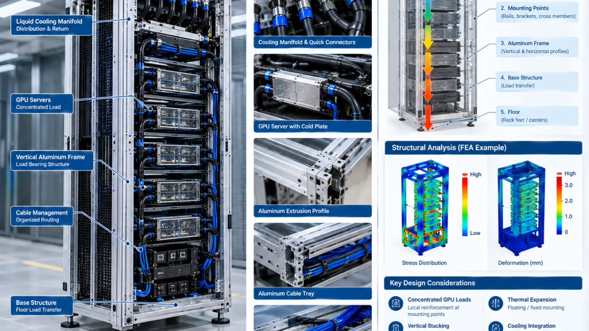
A dense AI rack may contain multiple heavy GPU servers stacked vertically, creating concentrated loads at specific mounting points. If the rack structure is not designed around these load paths, excessive deformation can affect equipment alignment, connectors, cooling interfaces, and long-term reliability.
This makes AI server rack load distribution a critical consideration in high-density computing infrastructure.
A properly engineered rack should answer four basic questions:
Where is the load generated?
Where is the load transferred?
Where is the structure most likely to deform?
How can the structure distribute the load efficiently?
For aluminum-based AI infrastructure, these questions are particularly important because aluminum offers low weight and excellent manufacturing flexibility, but its lower elastic modulus compared with steel means that geometry, section design, reinforcement, and load-path optimization must be carefully considered.
1. Why AI Server Rack Load Distribution Matters
A conventional IT rack may carry a relatively predictable combination of servers and networking equipment.
An AI rack can be very different.
A high-density configuration may contain:
- Multiple GPU servers
- High-power CPUs
- Large power supplies
- Busbars and power distribution hardware
- Liquid cooling manifolds
- Coolant hoses
- Cold plates
- Networking equipment
- Battery or backup-related components
- Extensive cabling
The total rack weight can become substantial.
However, total weight alone does not determine structural performance.
Two racks with the same total mass can behave very differently if one distributes the load evenly while the other concentrates most of the load around a few mounting points.
Therefore:
Total Rack Weight ≠ Actual Structural Loading Condition
The location and path of the load are equally important.
2. Understanding AI Rack Weight Distribution
The first step in AI rack weight distribution is to identify where the major masses are located.
For a typical high-density rack, the load may come from several levels:
Upper Section
May contain:
- Network switches
- Cable management
- Cooling distribution equipment
- Auxiliary equipment
Middle Section
Often contains the highest concentration of:
- GPU servers
- GPU chassis
- High-power compute modules
Lower Section
May contain:
- Power distribution equipment
- UPS-related components
- Heavy cooling interfaces
- Additional compute equipment
This means the center of gravity may not be located at the geometric center of the rack.
Engineers should therefore consider both:
Vertical Load Distribution
and
Front-to-Rear Load Distribution
3. Concentrated GPU Loads
One of the defining characteristics of AI infrastructure is the concentrated weight of GPU systems.
A GPU server can contain several large accelerator cards along with:
- Cooling plates
- Retention mechanisms
- Heat sinks
- Power connectors
- Structural brackets
The resulting load may be transferred through relatively small mounting areas.
This creates localized forces around:
- Rack rails
- Server mounting ears
- Chassis brackets
- Horizontal support members
- Vertical posts
A simple conceptual load path is:
GPU → Server Chassis → Rack Rail → Vertical Frame → Base → Floor
Each connection in this chain needs sufficient strength and stiffness.
4. The Difference Between Load Capacity and Stiffness
An important principle in server rack engineering is that strength and stiffness are not the same thing.
A structure may have enough strength to avoid failure but still deform too much under normal operating loads.
Excessive deformation can affect:
- Server insertion
- Rail alignment
- Connector engagement
- GPU positioning
- Cable connections
- Liquid cooling interfaces
- Door and panel alignment
For AI infrastructure, controlling deformation is therefore often as important as preventing structural failure.
This is especially relevant for aluminum structures.
Aluminum can provide excellent specific strength and low weight, but its elastic modulus is lower than that of steel. Therefore, an aluminum rack should not simply copy the dimensions of a steel rack and assume equivalent stiffness.
Instead:
Material Selection + Profile Geometry + Load Path + Reinforcement
must be considered together.
5. The Primary Load Path of an AI Server Rack
A properly designed rack should establish a clear and predictable load path.
For a typical GPU server:
GPU Module
↓
Server Chassis
↓
Rack Rail
↓
Horizontal Structural Member
↓
Vertical Aluminum Frame
↓
Base Structure
↓
Rack Foot / Caster
↓
Floor
The objective is to transfer loads through structural members rather than through thin enclosure panels or unnecessary secondary components.
This principle is fundamental to efficient rack engineering.
6. Vertical Stacking Creates Cumulative Loads
Vertical stacking is one of the most important considerations in high-density AI racks.
If multiple heavy servers are installed from top to bottom, the lower structural members may experience the combined load of equipment above them.
Conceptually:
Top Server → Local Rail Load
Second Server → Top + Second Load
Third Server → Top + Second + Third Load
and so on.
Therefore, structural loading can increase toward the lower sections of the rack.
This does not necessarily mean that every lower component must simply become thicker.
Instead, engineers can optimize:
- Vertical profile dimensions
- Cross-member geometry
- Rail attachment points
- Load distribution
- Bracket locations
- Base reinforcement
The goal is to distribute cumulative loads efficiently.
7. Vertical Aluminum Profiles as Primary Load-Bearing Members
For an aluminum AI rack, vertical extruded profiles can serve as the primary structural members.
A customized extrusion can incorporate:
- Internal cavities
- Reinforcing ribs
- Fastener channels
- Mounting slots
- Cable-routing features
- Bracket interfaces
This provides more structural efficiency than using a simple flat aluminum plate.
Profile geometry can be optimized for:
- Bending stiffness
- Torsional stiffness
- Buckling resistance
- Connection strength
- Manufacturing efficiency
The extrusion therefore becomes more than a frame component.
It becomes the primary load-transfer structure of the rack.
8. Horizontal Rails and Cross Members
Vertical posts alone cannot support a high-density AI rack.
Horizontal members connect the vertical structure and transfer loads between mounting points.
Typical components include:
- Server rails
- Cross beams
- Front mounting rails
- Rear support rails
- Intermediate braces
These members help:
- Distribute concentrated loads
- Reduce local deformation
- Improve rack rigidity
- Stabilize the vertical frame
- Control front-to-rear movement
The connection between the horizontal rail and vertical profile is particularly important.
A strong profile with a weak connection can still become a structural bottleneck.
9. Rack Rail Design Around GPU Servers
GPU servers are typically installed using rails or mounting brackets.
These interfaces can experience concentrated loads.
Engineers should consider:
- Fastener diameter
- Fastener quantity
- Hole spacing
- Local profile thickness
- Contact area
- Rail stiffness
- Installation tolerance
The mounting point should transfer the load into the main structure rather than allowing excessive local deformation.
For aluminum profiles, local reinforcement may be appropriate around heavily loaded attachment points.
10. Local Reinforcement for Concentrated Loads
Not every part of an AI rack needs the same structural capacity.
This creates an opportunity for localized reinforcement.
For example, reinforcement can be added around:
- GPU server rail connections
- Power supply mounting points
- Cooling manifold brackets
- Heavy equipment supports
- Rack lifting points
Possible approaches include:
- Reinforced extrusion geometry
- Additional brackets
- Gussets
- Doubling plates
- Internal inserts
- Larger connection areas
This can be more efficient than simply increasing the wall thickness of the entire rack.
The principle is:
Reinforce Where the Load Enters the Structure.
11. Front-to-Rear Load Distribution
AI server racks also experience loads in the front-to-rear direction.
A heavy server mounted toward the front of the rack can create a moment around the rack’s vertical structure.
This becomes particularly important when:
- Server chassis are deep
- GPUs are concentrated toward one side
- Cooling components extend beyond the main chassis
- Heavy power equipment is offset from the rack center
The design should therefore evaluate not only vertical compression but also:
- Bending moment
- Torsion
- Frame twisting
- Rail deflection
A rigid front-to-rear connection can help maintain overall rack stability.
12. Torsional Loads in High-Density AI Racks
Not all loads act symmetrically.
For example, a cooling manifold may be mounted on one side while heavy power components are located on the other.
This can create asymmetric loading.
Similarly, uneven server installation can create torsional forces.
Torsional deformation may affect:
- Door alignment
- Server rails
- Cooling connections
- Cable routing
- Structural joints
For this reason, a rack should be evaluated as a three-dimensional structure rather than as a simple vertical column.
13. Structural Bracing
Bracing can significantly improve rack stability.
Depending on the architecture, designers may use:
- Rear cross braces
- Side braces
- Corner brackets
- Diagonal members
- Reinforced cross beams
Bracing helps resist:
- Racking deformation
- Lateral loads
- Torsional movement
- Transportation vibration
For modular aluminum systems, the challenge is to provide sufficient structural rigidity without making the rack unnecessarily difficult to assemble or service.
14. Aluminum Profile Geometry for High-Density Racks
Aluminum extrusion provides an important design advantage: the cross-section itself can be engineered.
For example, instead of increasing material thickness everywhere, an extrusion can incorporate strategically positioned ribs.
A well-designed profile can provide:
High Moment of Inertia + Low Material Usage + Integrated Mounting Features
This is particularly valuable when the objective is to create a lightweight AI rack without sacrificing structural performance.
Profile design may consider:
- Section dimensions
- Rib placement
- Wall thickness
- Internal cavities
- Connection surfaces
- Fastener channels
The best profile is therefore application-specific.
15. Base Structure and Floor Load
The rack ultimately transfers its load to the floor.
This makes the base structure another important part of the load path.
The design should consider:
- Total rack mass
- Equipment distribution
- Rack feet
- Casters
- Leveling mechanisms
- Floor contact area
High-density AI equipment can create substantial localized floor loads.
The rack design should therefore work together with the facility’s floor and installation requirements.
16. Casters, Leveling Feet, and Static Load
A mobile rack introduces additional considerations.
When equipment is supported by casters, the load distribution may differ from the condition when the rack is positioned on leveling feet.
Engineers should consider:
- Static loading
- Rolling loads
- Impact during movement
- Floor transitions
- Rack stability
- Locking mechanisms
Moving a heavily loaded AI rack can introduce dynamic forces that are significantly different from normal stationary operation.
Therefore, transportation and installation conditions should be included in structural validation.
17. Liquid Cooling Adds Structural Loads
Liquid cooling introduces additional components into the rack architecture.
These may include:
- Manifolds
- Hoses
- Cold plates
- Quick connectors
- Coolant distribution assemblies
The cooling hardware adds weight, but that is not the only consideration.
Hoses and connectors can also introduce forces when:
- Connected
- Disconnected
- Bent
- Vibrating
- Thermally expanding
A good rack should therefore provide dedicated structural support for liquid cooling components.
The basic principle is:
Cooling Components Should Be Supported by the Frame, Not by the Server PCB or Flexible Hose.
18. Structural Interfaces With Liquid Cooling
A high-density AI rack may have a load path such as:
Manifold → Mounting Bracket → Aluminum Frame
while the fluid path is:
Manifold → Hose → Quick Connector → Cold Plate
Separating these two functions is important.
The fluid path should not be responsible for carrying structural loads.
This can reduce stress on:
- Connectors
- Hose fittings
- Cold plates
- Server chassis
and improve long-term reliability.
19. Mounting Points Are Structural Interfaces
Every mounting point represents a transition between components.
Examples include:
- GPU server to rail
- Rail to vertical profile
- Profile to base
- Manifold to bracket
- Bracket to frame
- Rack to floor
These interfaces can become structural weak points if not properly designed.
Engineers should evaluate:
- Local stress
- Contact pressure
- Fastener loading
- Pull-out resistance
- Shear loading
- Tolerance accumulation
The strongest profile cannot compensate for an inadequate connection.
20. Fastener Selection and Joint Design
Mechanical joints are particularly important in aluminum structures.
Potential joint methods include:
- Bolted connections
- T-slot fasteners
- Threaded inserts
- Captive nuts
- CNC-machined interfaces
- Riveted joints where appropriate
Threaded connections directly into aluminum may require careful consideration where frequent assembly or high loads are involved.
For high-cycle service interfaces, inserts or dedicated fastening features may provide better durability.
The joint should be designed according to its actual loading and maintenance requirements.
21. Thermal Expansion and Rack Alignment
AI racks operate under changing thermal conditions.
Aluminum expands and contracts with temperature.
If the rack combines aluminum with:
- Steel rails
- Copper cooling components
- Stainless-steel hardware
- Electronic assemblies
different materials may experience different dimensional changes.
This can influence:
- Rail alignment
- Cold plate positioning
- Connector engagement
- Fastener loading
The design should allow controlled thermal movement where appropriate while maintaining the required structural constraints.
22. Vibration and Transportation Loads
A server rack must survive more than stationary operating conditions.
Potential mechanical events include:
- Factory handling
- Truck transportation
- Installation
- Rack positioning
- Equipment insertion
- Fan vibration
- Pump vibration
AI racks with high equipment density can have significant mass and inertia.
Structural analysis should therefore consider dynamic loading where relevant.
The objective is to prevent:
- Joint loosening
- Frame deformation
- Component movement
- Rail damage
- Connector displacement
23. Structural Reinforcement Without Excessive Weight
A common response to increasing rack loads is simply to add more material.
This is rarely the most efficient approach.
A better strategy is to identify the actual load concentration points.
For example:
Heavy GPU Load
→ Reinforce Rail Interface
Large Manifold
→ Reinforce Manifold Bracket
High Rack-Level Bending
→ Increase Cross-Member Stiffness
Lateral Instability
→ Add Strategic Bracing
This approach can preserve the lightweight benefits of aluminum while increasing structural performance where it matters.
24. FEA for AI Rack Structural Design
Finite element analysis can help engineers understand how an AI rack responds to different loading conditions.
Typical simulations may include:
Static Structural Analysis
Evaluate:
- Server weight
- GPU loads
- Cooling equipment
- Power equipment
- Cable loads
Deformation Analysis
Identify:
- Rail deflection
- Frame displacement
- Local deformation
- Rack twisting
Modal Analysis
Evaluate:
- Natural frequencies
- Structural modes
- Vibration sensitivity
Buckling Analysis
Evaluate:
- Vertical profile stability
- Compression members
- Slender structural sections
Simulation can help identify weak points before physical prototypes are manufactured.
25. Physical Validation Is Still Essential
FEA provides valuable design information, but physical testing remains important.
A prototype rack can be evaluated for:
- Static loading
- Deflection
- Joint strength
- Rack alignment
- Vibration
- Transportation
- Assembly repeatability
A practical development process is:
CAD → FEA → Prototype → Load Test → Vibration Test → Assembly Validation → Design Optimization
This is particularly useful for custom aluminum rack structures where profile geometry and connection design may differ significantly from standard server racks.
26. Designing for Manufacturing
Structural performance is only one part of successful rack development.
The design must also be manufacturable.
For aluminum AI racks, a practical manufacturing architecture may combine:
- Extruded aluminum profiles
- CNC-machined brackets
- Sheet-metal panels
- Standard fasteners
- Custom reinforcement components
A typical process may be:
Extrusion → Cutting → CNC Machining → Surface Treatment → Sub-Assembly → Final Assembly → Inspection
This hybrid approach can provide both structural performance and manufacturing flexibility.
27. Serviceability and Structural Design Must Coexist
Structural reinforcement should not make the rack impossible to service.
For example, adding a cross brace directly in front of a GPU removal path may improve stiffness while creating a serious maintenance problem.
Therefore, structural design should be coordinated with:
- GPU removal
- Server insertion
- Cable routing
- Cooling connections
- Power maintenance
- Access panels
The best rack architecture balances:
Structural Rigidity ↔ Component Accessibility
rather than maximizing one at the expense of the other.
28. Designing for Future AI Rack Configurations
AI hardware evolves quickly.
A rack designed for one generation of GPUs may later need to accommodate:
- Heavier accelerator modules
- Higher rack power
- Different chassis dimensions
- New cooling architectures
- More networking equipment
A modular aluminum frame can make future changes easier.
Potential design features include:
- Adjustable mounting rails
- Reconfigurable cross members
- Modular brackets
- Replaceable reinforcement sections
- Standardized connection points
This creates a structural platform rather than a single-purpose rack.
29. Common Mistakes in AI Rack Load Distribution
Mistake 1: Designing around total weight only
The location of the load can be more important than the total mass.
Mistake 2: Ignoring concentrated GPU loads
Heavy equipment can create localized stress at rails and mounting points.
Mistake 3: Using aluminum dimensions copied from steel designs
Equivalent dimensions do not automatically provide equivalent stiffness.
Mistake 4: Reinforcing everything equally
Uniform reinforcement can add unnecessary weight.
Mistake 5: Ignoring connection strength
Structural members are only as strong as their critical joints.
Mistake 6: Ignoring front-to-rear moments
Deep and heavy GPU servers can create significant bending effects.
Mistake 7: Treating cooling hardware as structurally independent
Manifolds and connectors need dedicated support.
Mistake 8: Designing without service access
Structural members should not obstruct routine maintenance.
30. A Practical AI Server Rack Engineering Workflow
A systematic process can reduce structural redesign during development.
Step 1: Define Equipment Loads
Identify:
- Server mass
- GPU mass
- Power equipment
- Cooling equipment
- Cable loads
Step 2: Map the Center of Gravity
Determine:
- Vertical center of gravity
- Front-to-rear distribution
- Left-to-right asymmetry
Step 3: Define the Load Paths
Map:
Server → Rail → Frame → Base → Floor
Step 4: Identify Critical Interfaces
Review:
- Rail connections
- Cross members
- Brackets
- Base joints
- Cooling supports
Step 5: Optimize Aluminum Profile Geometry
Consider:
- Section dimensions
- Ribs
- Wall thickness
- Connection features
Step 6: Add Local Reinforcement
Strengthen only where the loads require it.
Step 7: Perform Structural Simulation
Evaluate:
- Stress
- Deformation
- Buckling
- Vibration
Step 8: Build a Prototype
Verify actual assembly and component compatibility.
Step 9: Conduct Physical Testing
Validate structural performance under representative conditions.
Step 10: Optimize for Production
Refine:
- Extrusion design
- CNC processes
- Assembly sequence
- Fasteners
- Surface treatment
31. Aluminum as a Structural Platform for AI Infrastructure
The role of aluminum in AI infrastructure is expanding beyond individual brackets and panels.
A properly engineered aluminum frame can integrate:
- GPU support
- Server mounting
- Cable management
- Liquid cooling supports
- Thermal structures
- Power equipment interfaces
- Service access
This creates a unified mechanical platform.
The value of aluminum is therefore not simply its low density.
Its greater advantage can come from the ability to combine:
Extrusion + Machining + Structural Design + Thermal Integration + Modular Assembly
within one infrastructure architecture.
Design the Load Path Before Designing the Rack
High-density AI server racks require a different approach to structural engineering.
The challenge is not simply determining whether a rack can carry a certain total weight. Engineers must understand where the weight is concentrated, how vertical loads accumulate, how GPU server rails transfer forces, how mounting points behave, and how those forces ultimately reach the floor.
For aluminum structures, this becomes even more important.
A successful AI server rack load distribution strategy combines:
Concentrated Load Analysis → Vertical Load Distribution → Rail Design → Aluminum Profile Geometry → Local Reinforcement → Joint Engineering → Base Structure → Physical Validation
The goal is not to build the heaviest rack.
It is to build a rack in which the load follows a clear, controlled, and efficient structural path.
For high-density AI infrastructure, that means designing the GPU rack structural load, frame geometry, mounting points, cooling supports, and service interfaces as one integrated system.
When structural load distribution is engineered from the beginning, an aluminum rack can become more than a lightweight support structure. It can serve as a modular physical platform for the next generation of high-density AI computing.
Load Source → Structural Interface → Aluminum Frame → Reinforcement → Base → Floor
That is the foundation of reliable server rack engineering.