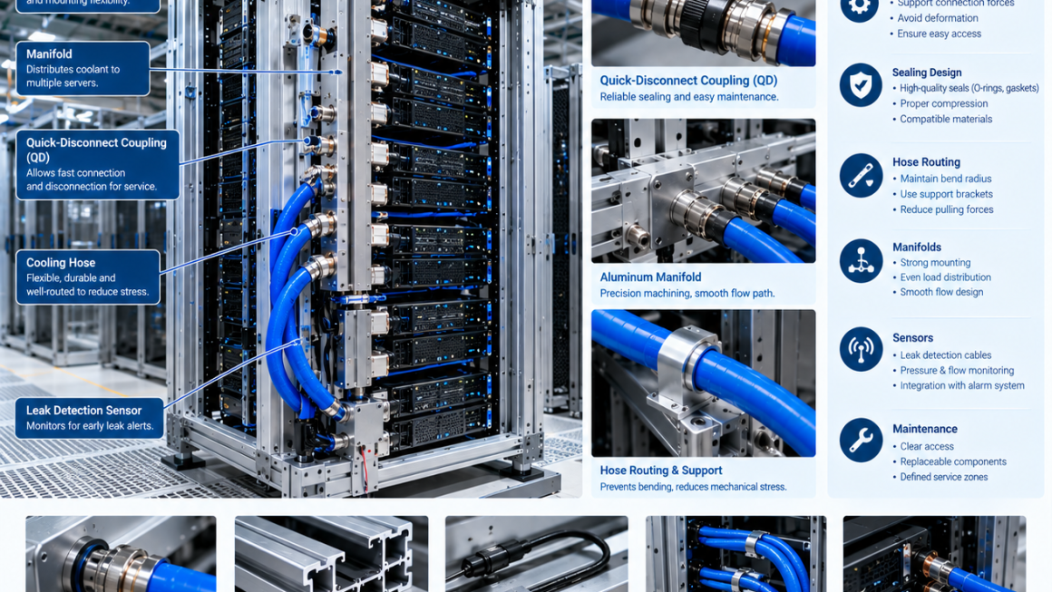
As AI servers become more powerful, liquid cooling is becoming an increasingly important part of data center infrastructure.
High-density GPU systems may include:
- Cold plates
- Coolant distribution units
- Manifolds
- Quick-disconnect couplings
- Flexible cooling hoses
- Aluminum structural frames
- Sealing components
- Leak detection sensors
With more fluid connections inside and around high-value computing equipment, AI liquid cooling leak prevention is becoming a critical engineering requirement.
However, leak prevention should not begin with a sensor.
A reliable cooling system starts with mechanical design.
The most effective approach combines:
Mechanical Structure + Sealing + Hose Routing + Connection Design + Leak Detection + Maintenance
A sensor can detect a leak.
Good mechanical engineering helps prevent the leak from happening in the first place.
1. Why Leak Prevention Matters in AI Liquid Cooling
Liquid cooling introduces a fundamentally different reliability consideration compared with conventional air-cooled servers.
Air cooling primarily depends on:
- Fans
- Heat sinks
- Air channels
- Filters
Liquid cooling adds:
- Coolant
- Hoses
- Connectors
- Manifolds
- Seals
- Pumps
- Valves
- Fluid interfaces
A small leak can potentially affect:
- Server electronics
- GPU modules
- Power components
- Rack structures
- Adjacent equipment
The potential consequences make cooling reliability an important part of AI infrastructure design.
The objective is therefore not simply to detect leaks quickly.
It is to create a system with multiple layers of protection:
Prevent → Contain → Detect → Isolate → Service
2. Leak Prevention Starts With Mechanical Design
One of the most important principles in AI liquid cooling is:
Leak prevention should be considered before the cooling system is assembled.
Mechanical design influences:
- Connector alignment
- Hose bending
- Sealing pressure
- Manifold deformation
- Fastener loading
- Thermal expansion
- Vibration
- Maintenance access
A poorly designed mechanical interface can create additional stress on seals and connectors.
Even a high-quality sealing component can eventually fail if it is continuously subjected to:
- Excessive movement
- Misalignment
- Compression
- Temperature cycling
- Hose pulling forces
Therefore:
Cooling reliability is partly a mechanical engineering problem.
3. The Main Sources of Liquid Cooling Leakage
Leaks can occur at many points in an AI cooling system.
Typical risk areas include:
Cold Plate Connections
Potential issues:
- Seal damage
- Improper assembly
- Thermal movement
- Connection stress
Quick-Disconnect Couplings
Potential issues:
- Incorrect engagement
- Damaged sealing elements
- Excessive hose force
- Mechanical misalignment
Manifold Interfaces
Potential issues:
- Thread leakage
- Joint deformation
- Poor sealing
- Local stress
Hose Connections
Potential issues:
- Excessive bending
- Abrasion
- Improper clamping
- Aging
Tubing and Fittings
Potential issues:
- Material incompatibility
- Mechanical vibration
- Pressure cycling
The complete fluid path should therefore be considered during the design stage.
4. Designing Reliable Cooling System Sealing
Sealing is one of the most important elements of liquid cooling reliability.
Depending on the application, systems may use:
- O-rings
- Gaskets
- Sealing washers
- Thread seals
- Compression fittings
- Specialized connector seals
The sealing method must match the application.
Important variables include:
- Coolant chemistry
- Temperature
- Pressure
- Surface finish
- Compression
- Dimensional tolerance
- Assembly method
A seal should never be selected independently from the surrounding materials and operating conditions.
5. O-Ring Design in AI Cooling Systems
O-rings are widely used in fluid interfaces.
A reliable O-ring design requires control of:
- Groove dimensions
- Compression
- Surface finish
- Material compatibility
- Temperature range
Potential problems can occur when an O-ring is:
- Over-compressed
- Under-compressed
- Cut during assembly
- Exposed to incompatible coolant
- Installed on a damaged surface
Therefore, precision machining and inspection of the sealing groove can be just as important as the O-ring material itself.
6. Aluminum Structures and Sealing Interfaces
Aluminum is increasingly used in AI liquid cooling infrastructure because it offers:
- Low weight
- Good strength-to-weight characteristics
- Good thermal conductivity
- Excellent extrusion capability
- Good machinability
However, aluminum structures surrounding a fluid interface must be designed with appropriate stiffness and dimensional stability.
For example, an aluminum manifold mounting structure should prevent excessive deformation during:
- Assembly
- Pressure operation
- Hose connection
- Thermal cycling
A sealing interface requires controlled geometry.
Structural movement can eventually become a sealing problem.
7. Manifold Design for Leak Prevention
A manifold distributes coolant to multiple cooling branches.
Because a manifold may contain many connection points, its mechanical design is important for overall system reliability.
A well-designed manifold should consider:
- Wall thickness
- Port geometry
- Connector spacing
- Mounting locations
- Internal flow paths
- Pressure loads
- Thermal expansion
The manifold should also be adequately supported.
If the manifold moves excessively when hoses are connected or disconnected, mechanical loads can be transferred to the sealing interfaces.
8. Hose Routing as a Leak Prevention Strategy
Hose routing is often underestimated.
A hose should not be treated simply as a flexible pipe between two components.
It is also a source of mechanical force.
A poorly routed hose may create:
- Pulling force
- Bending force
- Twisting
- Compression
- Abrasion
These forces can be transferred to:
Hose → QD → Manifold → Bracket → Aluminum Structure
A better routing strategy allows the hose to move naturally without placing unnecessary load on the connector.
9. Bend Radius and Cooling Hose Reliability
Every cooling hose has a recommended minimum bend radius.
Forcing a hose into a tighter bend can create additional mechanical stress.
Engineers should consider:
- Hose diameter
- Construction
- Operating pressure
- Temperature
- Installation movement
- Maintenance requirements
The QD location, manifold location, and aluminum support structure should therefore be designed together.
A practical design sequence is:
QD Position
→ Hose Exit Direction
→ Required Bend Radius
→ Support Point
→ Manifold Location
This reduces unnecessary mechanical loading.
10. Avoiding Hose-Induced Connector Loads
A common mistake is allowing the hose to support its own weight through the connector.
For larger cooling hoses, this can create significant loads.
The better approach is to provide:
- Hose supports
- Routing brackets
- Strain relief
- Appropriate clamps
The connector should primarily perform its intended fluid connection function.
The surrounding mechanical structure should carry the hose’s mechanical load where practical.
11. Quick-Disconnect Couplings and Leak Prevention
Quick-disconnect couplings are valuable because they allow servers to be serviced without permanently disconnecting the entire cooling system.
However, QDs also introduce another sealing interface.
Potential risks include:
- Incomplete connection
- Seal damage
- Contamination
- Mechanical misalignment
- Excessive hose force
The QD should therefore have:
- Adequate structural support
- Clear service access
- Correct alignment
- Sufficient hose clearance
A QD should never be forced into alignment by the hose itself.
12. Thermal Expansion and Cooling System Sealing
AI liquid cooling systems operate through temperature changes.
When temperature changes:
- Aluminum expands and contracts.
- Copper components move differently.
- Hoses change dimensions.
- Manifolds move relative to the rack.
If these movements are completely constrained, additional loads can be transferred into seals and connectors.
Therefore, engineers should define:
- Fixed points
- Floating points
- Expansion directions
- Flexible hose sections
The goal is controlled movement rather than zero movement.
13. Leak Detection: Why Sensors Still Matter
Even with good mechanical design, no complex cooling system can rely on prevention alone.
Liquid cooling leak detection provides a second layer of protection.
Sensors can help identify abnormal conditions before a small problem becomes a larger event.
Possible detection approaches include:
- Water or coolant sensing cables
- Point leak sensors
- Drip trays
- Moisture sensors
- Pressure monitoring
- Flow monitoring
- Coolant level monitoring
Different technologies detect different failure modes.
Therefore, sensor selection should follow the system architecture.
14. Point Leak Sensors
Point sensors can be positioned near high-risk areas.
Potential locations include:
- Under manifolds
- Near QDs
- Below hose connections
- Near cold plate interfaces
- Inside containment areas
They are particularly useful where a small amount of leaked coolant is likely to accumulate.
However, point sensors depend heavily on correct placement.
A sensor installed several centimeters away from the actual leak may detect the problem later than expected.
15. Leak Detection Cables
Leak detection cables can provide broader coverage.
They may be installed around:
- Rack cooling zones
- Manifolds
- Equipment floors
- Cooling distribution areas
This approach can be useful for larger installations where many potential leak points exist.
The sensor system should be integrated with facility monitoring and alarm systems where appropriate.
16. Pressure and Flow Monitoring
Not every leak produces visible liquid immediately.
A small leak may instead appear as an abnormal change in:
- Pressure
- Flow
- Coolant level
Monitoring these parameters can provide another layer of protection.
For example:
Unexpected pressure decrease
Unexpected flow imbalance
may indicate a potential fluid-system problem.
However, these signals should be interpreted within the context of normal system operation.
Pump startup, valve changes, and maintenance activities can also change pressure and flow.
17. Combining Mechanical and Electronic Protection
A reliable AI cooling system should use multiple layers.
Layer 1 — Mechanical Prevention
- Proper connector design
- Correct sealing
- Controlled hose routing
- Structural support
Layer 2 — Containment
- Drip trays
- Drainage
- Controlled fluid paths
Layer 3 — Detection
- Leak sensors
- Pressure monitoring
- Flow monitoring
Layer 4 — Response
- Alarm
- Pump shutdown where appropriate
- Isolation
- Maintenance procedure
This creates a more robust protection architecture than relying on a single sensor.
18. Designing for Leak Containment
Leak prevention does not mean assuming that leakage will never occur.
Engineers should also consider:
Where would the coolant go if a connection failed?
Mechanical structures can help control the direction and location of leaked fluid.
Potential design features include:
- Drainage channels
- Collection trays
- Sealed compartments
- Accessible inspection areas
The objective is to prevent leaked coolant from reaching sensitive electronics whenever practical.
19. Aluminum Structures for Leak Containment
Aluminum can also play a role in physical containment.
For example, an aluminum support structure may incorporate:
- Drainage features
- Protective panels
- Service openings
- Hose supports
- Manifold brackets
Extruded aluminum profiles can be designed with integrated channels and mounting features.
CNC machining can then create:
- Drain ports
- Connector openings
- Inspection holes
- Precision mounting surfaces
This makes the mechanical structure part of the leak-management strategy.
20. Corrosion Considerations After a Leak
Leak prevention also connects directly with material compatibility.
If coolant contacts aluminum, copper, steel, or other materials, the consequences depend on:
- Coolant chemistry
- Exposure duration
- Temperature
- Material combination
- Surface treatment
Mixed-metal systems require particular attention to galvanic corrosion.
Therefore, AI server cooling reliability should consider both:
Leak Prevention
and
Material Compatibility
A cooling system may prevent long-term corrosion only if the coolant and material combination are properly validated.
21. Electrical Considerations
AI servers contain sensitive electrical and electronic components.
Therefore, the cooling system should consider electrical consequences of coolant leakage.
Important areas include:
- GPU boards
- Power supplies
- Busbars
- Connectors
- Grounding structures
Mechanical design should minimize the possibility that leaked coolant can reach sensitive electrical components.
Where required, isolation and grounding strategies should be incorporated into the equipment design.
22. Serviceability Is Part of Leak Prevention
Maintenance is one of the most important opportunities to prevent future leaks.
A difficult-to-access connector is more likely to be:
- Improperly connected
- Damaged during service
- Contaminated
- Misaligned
A serviceable design provides:
- Clear access
- Adequate hand clearance
- Visible connection points
- Replaceable hoses
- Accessible inspection areas
Good serviceability reduces the probability of maintenance-related leakage.
23. Designing Aluminum Cooling Structures for Maintenance
Aluminum extrusion can provide a modular mechanical platform for serviceable cooling infrastructure.
Possible features include:
- Adjustable brackets
- Mounting channels
- Removable panels
- Hose supports
- Manifold supports
This allows engineers to create defined service zones around the cooling interfaces.
Instead of designing the structure only for initial assembly, the design should also consider:
How will a technician replace this component five years later?
That question often reveals problems that are invisible during initial installation.
24. Manufacturing Quality and Leak Prevention
Good design must be supported by manufacturing quality.
For aluminum cooling components, relevant controls may include:
CNC Machining
Controls:
- Port dimensions
- O-ring grooves
- Thread accuracy
- Flatness
Deburring
Prevents sharp edges from damaging:
- Seals
- Hoses
- O-rings
Surface Treatment
Supports:
- Corrosion resistance
- Wear resistance
Pressure Testing
Verifies:
- Structural integrity
- Connection reliability
Leak Testing
Provides final validation of the fluid path.
25. Pressure and Leak Testing
Pressure testing should be defined according to the actual cooling system and component requirements.
Possible validation methods include:
- Hydrostatic testing
- Pneumatic testing where appropriate
- Pressure decay testing
- Helium or tracer-gas methods for specialized applications
- Functional coolant loop testing
The selected method should match the component, pressure level, fluid, and safety requirements.
Testing should be performed not only on individual components but also on representative assemblies where practical.
26. Thermal Cycling Tests
A cooling system may operate through repeated temperature changes.
Therefore, testing should consider:
Cold → Operating Temperature → Cold
Repeated cycling can reveal:
- Seal movement
- Material expansion differences
- Joint loosening
- Hose changes
- Manifold deformation
Thermal cycling is particularly useful for validating interfaces between aluminum, copper, polymers, and sealing materials.
27. Common Leak Prevention Mistakes
Mistake 1: Relying Only on Sensors
A sensor detects a problem but does not prevent mechanical failure.
Mistake 2: Ignoring Hose Forces
Poor hose routing can continuously load the connector.
Mistake 3: Overlooking Thermal Expansion
Rigidly constraining different materials can create unnecessary sealing stress.
Mistake 4: Designing for Assembly but Not Maintenance
Service operations can introduce new leakage risks.
Mistake 5: Poor Surface Preparation
Scratches, burrs, or contamination can compromise sealing surfaces.
Mistake 6: Treating the Manifold as Only a Fluid Component
The manifold also transfers mechanical loads.
Mistake 7: Ignoring Material Compatibility
Coolant, aluminum, copper, seals, fittings, and coatings must be considered as one system.
28. A Practical AI Liquid Cooling Leak Prevention Workflow
A practical engineering workflow can be structured as follows:
Step 1 — Map the Complete Cooling Loop
Identify every:
- Hose
- QD
- Manifold
- Cold plate
- Valve
- Fitting
Step 2 — Identify High-Risk Interfaces
Evaluate:
- Pressure
- Movement
- Temperature
- Service frequency
Step 3 — Design the Mechanical Support
Define:
- Aluminum profiles
- Brackets
- Manifold supports
- Hose supports
Step 4 — Design the Sealing System
Define:
- Seal material
- Groove geometry
- Compression
- Surface finish
Step 5 — Design Leak Containment
Determine:
- Drainage
- Collection
- Inspection zones
Step 6 — Add Detection
Select:
- Point sensors
- Detection cables
- Pressure monitoring
- Flow monitoring
Step 7 — Validate
Perform:
- Pressure testing
- Leak testing
- Thermal cycling
- Vibration testing
- Service-cycle testing
Step 8 — Establish Maintenance Procedures
Define:
- Inspection intervals
- Connector replacement
- Hose replacement
- Coolant monitoring
29. From Component Design to System Reliability
A reliable AI cooling system cannot be created by optimizing individual components independently.
For example:
A high-quality QD can still perform poorly if:
- The hose is badly routed.
- The bracket is too flexible.
- The manifold is misaligned.
- The structure restricts thermal movement.
Similarly, an excellent O-ring cannot compensate for:
- Poor groove geometry
- Damaged sealing surfaces
- Incorrect assembly
This is why system-level mechanical engineering matters.
The reliability chain is:
Component Quality
→ Interface Design
→ Structural Integration
→ Fluid System Design
→ Detection
→ Maintenance
30. Future AI Cooling Reliability
As AI rack power density increases, cooling systems will become increasingly integrated with mechanical infrastructure.
Future systems are likely to require:
- More cooling connections
- Higher coolant flow
- Better monitoring
- More modular service interfaces
- Improved leak containment
- Greater automation
This will increase the importance of mechanical design around fluid interfaces.
Aluminum structures can contribute through:
- Lightweight rack structures
- Manifold supports
- QD brackets
- Hose management
- Protective panels
- Modular service structures
The mechanical infrastructure surrounding the cooling system will become increasingly important to overall reliability.
Leak Prevention Is a System-Level Design Problem
Reliable AI liquid cooling requires more than choosing a good connector or installing a leak sensor.
AI liquid cooling leak prevention begins with mechanical design.
The complete system should consider:
- Sealing
- Hose routing
- QD interfaces
- Manifold support
- Aluminum structural stiffness
- Thermal expansion
- Material compatibility
- Leak containment
- Sensor placement
- Maintenance access
The most effective strategy is layered:
Prevent
→ Contain
→ Detect
→ Isolate
→ Maintain
For high-density AI infrastructure, this approach can help improve AI server cooling reliability while making liquid cooling systems easier to inspect, service, and scale.
The key principle is simple:
A leak detection system should not be the first line of defense. Good mechanical design should be.