



As AI servers continue to adopt higher-power GPUs and increasingly dense computing architectures, liquid cooling systems must deliver sufficient coolant flow to multiple heat-generating components while maintaining stable operating conditions.
In these systems, cold plates, coolant manifolds, distribution blocks, connecting channels, and fittings work together as a fluid network. Their internal geometry determines how easily coolant moves through the system and how flow is distributed among different cooling branches.
Two important engineering parameters are pressure drop and flow distribution.
Pressure drop describes the reduction in fluid pressure as coolant moves through a component or flow path. Flow distribution describes how the available coolant flow is divided among different branches or cooling components.
These parameters are closely related. A cooling system may have a relatively low overall pressure drop but still distribute coolant unevenly. Conversely, a cold plate with relatively high flow resistance may provide effective thermal performance under a properly designed operating condition.
For AI liquid cooling hardware manufacturers, evaluating flow performance requires more than inspecting external dimensions or the apparent complexity of internal channels.
This article explains how channel cross-sections, local resistance, branch flow, connection interfaces, and internal geometry influence pressure drop and flow distribution in AI liquid cooling systems.
1. Understanding Pressure Drop in AI Liquid Cooling Systems
When coolant flows through a cold plate, manifold, pipe, or connector, it encounters resistance caused by friction and changes in flow direction or geometry.
The pressure difference between the inlet and outlet is commonly referred to as pressure drop.
Several factors influence pressure drop:
- Coolant flow rate
- Internal channel dimensions
- Channel length
- Surface roughness
- Fluid viscosity and density
- Bends, turns, and contractions
- Internal obstructions
- Inlet and outlet geometry
In a simplified system, the total pressure drop can be considered as the combined contribution of different components and flow sections.
For example, a liquid cooling loop may include:
- Coolant distribution manifold
- Supply hose and fittings
- Server-level distribution block
- GPU cold plate
- Return hose and connections
- Rack-level return manifold
Each component contributes to the hydraulic resistance of the complete circuit.
This means that optimizing one component does not automatically optimize the entire cooling system.
A cold plate with carefully designed internal channels may still operate inefficiently if the connecting fittings, distribution manifold, or upstream piping introduce excessive resistance.
2. Channel Cross-Section: How Geometry Influences Flow Resistance
The cross-sectional geometry of a cooling channel is one of the fundamental factors affecting hydraulic performance.
Common channel configurations include:
- Circular channels
- Rectangular channels
- Square channels
- Multi-channel extruded profiles
- Machined microchannels
- Complex internal passages
Each geometry has different hydraulic characteristics.
Circular channels
Circular channels are commonly used in pipes and connecting passages.
Their advantages include relatively straightforward manufacturing, established fluid-flow calculations, and the absence of sharp internal corners.
However, the available cross-sectional area and hydraulic diameter must still be selected according to the required flow rate and pressure conditions.
Rectangular channels
Rectangular channels are frequently used in aluminum cold plates and liquid cooling structures.
They can provide a relatively large wetted surface area within a compact component.
However, their hydraulic behavior depends on both channel width and height. Two rectangular channels with the same cross-sectional area may not have identical pressure-drop characteristics.
Multi-channel structures
Multiple parallel channels can increase the available heat-transfer area and divide coolant flow across different regions.
However, the number of channels alone does not determine performance.
Channel dimensions, distribution geometry, flow rate, surface condition, and manufacturing tolerances all influence the final result.
Hydraulic diameter
For non-circular channels, hydraulic diameter is commonly used to characterize the relationship between flow area and wetted perimeter.
It is defined as:
[
D_h=\frac{4A}{P_w}
]
Where:
- (D_h) = hydraulic diameter
- (A) = internal flow cross-sectional area
- (P_w) = wetted perimeter
This parameter helps engineers compare different channel geometries, although it does not fully describe every aspect of complex internal flow.
The key point is that channel cross-sectional area alone is not enough to predict hydraulic performance.
3. Local Resistance: The Impact of Bends, Turns, and Flow Transitions
Pressure loss does not occur only along straight cooling channels.
Local geometric features can also contribute significantly to hydraulic resistance.
Examples include:
- Sharp bends
- Sudden contractions
- Sudden expansions
- Branch junctions
- Internal steps
- Inlet and outlet transitions
- Changes in flow direction
These features disturb the flow field and can generate additional energy losses.
In engineering calculations, local pressure loss is often expressed as:
[
\Delta P_{local}=K\frac{\rho v^2}{2}
]
Where:
- (\Delta P_{local}) = local pressure drop
- (K) = local loss coefficient
- (\rho) = coolant density
- (v) = reference flow velocity
The loss coefficient depends on the specific geometry and flow conditions.
Why internal transitions matter
Consider a cold plate with a relatively large inlet port connected to a much narrower internal channel.
If the transition is poorly designed, the coolant may experience a sudden change in velocity and flow direction.
Similarly, a sharp internal turn may introduce separation and recirculation, increasing pressure loss.
A smoother transition can sometimes reduce these losses, but the result depends on the complete geometry and operating conditions.
Engineers should therefore examine the internal flow path rather than evaluating only the inlet and outlet dimensions.
4. Flow Distribution in Coolant Manifolds
A coolant manifold distributes liquid from a common supply passage into multiple branches.
In AI servers, these branches may supply several GPU cold plates, CPU cooling components, or other heat-generating devices.
The manifold must distribute coolant in a way that meets the flow requirements of each branch.
However, equal branch dimensions do not necessarily produce equal flow rates.
Flow distribution depends on the hydraulic resistance of each branch and the pressure conditions at its inlet and outlet.
Parallel flow branches
In a parallel cooling arrangement, coolant enters a common distribution region and divides into multiple paths.
Each branch experiences a pressure difference between its inlet and outlet.
At steady state, branches connected between the same two pressure nodes experience the same pressure difference, but their individual flow rates depend on their hydraulic characteristics.
For example:
- A branch with lower resistance may receive more flow.
- A branch with higher resistance may receive less flow.
- Different channel lengths can produce different pressure losses.
- Variations in fittings and internal geometry can change branch resistance.
This can create uneven cooling conditions across different components.
Why manifold geometry matters
Several manifold design parameters influence flow distribution:
Main passage dimensions
The cross-section of the main supply and return passages affects how pressure changes along the manifold.
Branch location
The position of each outlet relative to the inlet can influence local pressure conditions.
Branch geometry
Different branch diameters, lengths, bends, and restrictions can create different hydraulic resistance.
Supply and return arrangement
The relationship between supply and return paths affects the pressure difference available to each cooling branch.
A manifold should therefore be designed as part of the complete cooling network rather than treated as a simple distribution block.
5. Flow Imbalance: Why Equal Connections Do Not Guarantee Equal Cooling
One common design assumption is that identical cold plates connected to a common manifold will automatically receive equal coolant flow.
In practice, this is not always true.
Even when the cold plates have identical external dimensions, small differences in internal geometry, branch resistance, connection interfaces, and assembly conditions may influence flow distribution.
Potential causes of flow imbalance include:
- Different hose lengths
- Unequal fitting resistance
- Variations in channel dimensions
- Different numbers of bends
- Unequal manifold pressure conditions
- Manufacturing tolerances
- Partial obstruction or contamination
For high-density GPU systems, uneven coolant distribution may result in different thermal conditions between components.
A component receiving insufficient coolant flow may experience a higher temperature rise, even if the overall cooling system appears to have sufficient pump capacity.
Evaluating flow imbalance
Engineers should compare the actual flow rate of individual branches rather than relying only on total system flow.
Depending on the system architecture, evaluation may involve:
- Branch flow measurements
- Pressure measurements at selected locations
- Flow visualization
- Thermal mapping
- Computational fluid dynamics (CFD)
- Testing under different operating conditions
The objective is to understand how the coolant is distributed across the complete system.
6. Connection Interfaces: Small Components Can Influence System Performance
The external connection between cooling components is another important source of hydraulic resistance.
Common interfaces include:
- Threaded fittings
- Quick-disconnect connectors
- Hose adapters
- Manifold ports
- Transition joints
- Internal sealing connections
A connection may have a relatively small external footprint but introduce a meaningful restriction inside the fluid path.
For example, the internal passage of a fitting may be narrower than the connected hose or manifold channel.
A sudden contraction followed by expansion can increase local pressure loss.
Quick-disconnect connectors may also introduce internal restrictions depending on their design and size.
Interface design considerations
When selecting or designing connection interfaces, engineers should evaluate:
- Internal passage diameter
- Flow-path continuity
- Port alignment
- Transition geometry
- Connector pressure-drop characteristics
- Sealing arrangement
- Compatibility with the specified coolant
- Assembly and maintenance requirements
A fitting should not be selected solely because its external thread or connection size matches the surrounding hardware.
The internal flow passage must also be considered.
This is particularly important when multiple fittings are installed in series throughout a compact AI rack cooling circuit.
7. Internal Geometry of Aluminum Cold Plates
Aluminum cold plates are widely used in liquid cooling hardware because aluminum offers a combination of low density, thermal conductivity, and manufacturing flexibility.
However, the thermal and hydraulic performance of an aluminum cold plate depends heavily on its internal geometry.
Common designs include:
Straight parallel channels
These channels provide relatively straightforward flow paths and can be manufactured using extrusion or machining.
Their hydraulic performance depends on channel dimensions, length, surface condition, and flow distribution at the inlet.
Serpentine channels
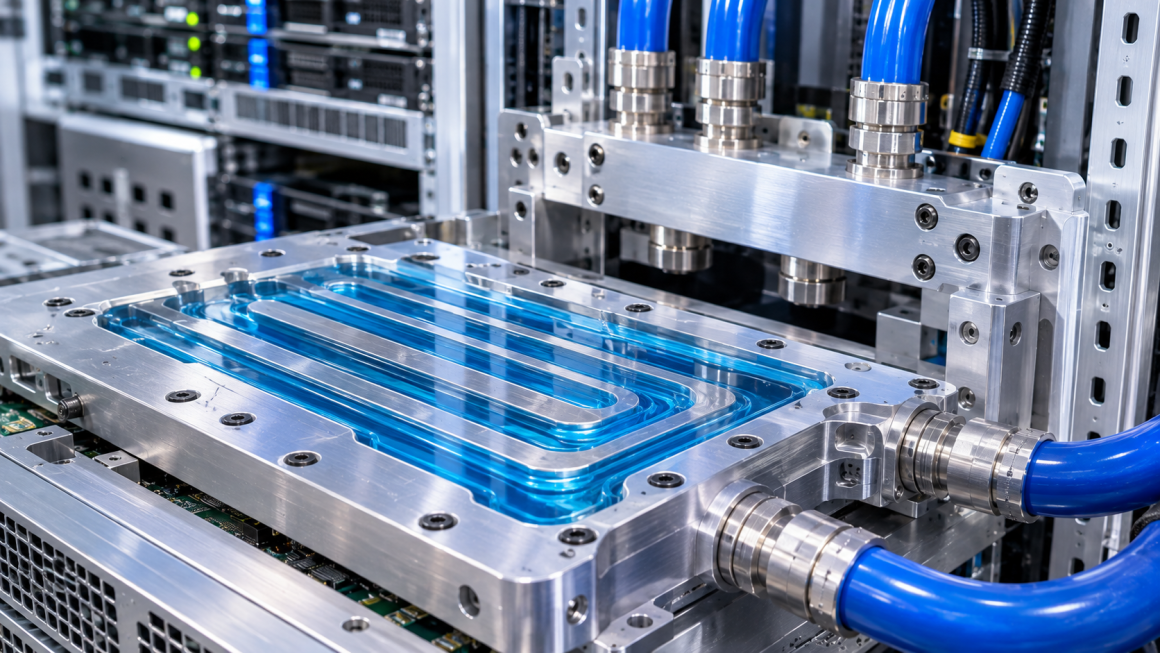
Serpentine designs route coolant through a continuous winding path.
They can provide extended flow paths within a compact footprint, but repeated turns may increase pressure drop.
Multi-pass channels
Multi-pass structures guide coolant through several sections before it exits the cold plate.
Their performance depends on the interaction between passage dimensions, flow direction changes, and internal distribution.
Pin-fin structures
Pin-fin geometries increase the wetted surface area and can enhance fluid mixing.
However, they may also introduce additional hydraulic resistance.
The actual performance depends on pin dimensions, spacing, arrangement, and operating flow conditions.
Microchannel structures
Microchannels provide small hydraulic dimensions and can create high heat-transfer surface area relative to volume.
However, their smaller passages can increase flow resistance and make manufacturing cleanliness and dimensional consistency particularly important.
No single internal geometry is automatically best for every AI cooling application.
The appropriate design depends on the heat load, allowable pressure drop, coolant properties, pump capability, required flow rate, and manufacturing constraints.
8. The Relationship Between Pressure Drop and Thermal Performance
Pressure drop and thermal performance must be evaluated together.
Increasing coolant flow may improve heat removal under many operating conditions, but it also generally requires additional pumping power.
Similarly, increasing internal surface area or introducing more complex flow structures may improve heat transfer, but these changes can also increase hydraulic resistance.
A useful design question is therefore not simply:
“How can the cold plate achieve the lowest possible temperature?”
Instead, engineers should consider:
“Can the cold plate achieve the required thermal performance within the available flow rate and pressure budget?”
A simplified pressure-flow relationship
For many turbulent-flow applications, pressure drop can be approximated as increasing with the square of flow rate over a defined operating range:
[
\Delta P \propto Q^2
]
Where:
- (\Delta P) = pressure drop
- (Q) = volumetric flow rate
This is a simplified relationship, not a universal rule. Actual behavior depends on flow regime, geometry, coolant properties, and system characteristics.
The pumping power required by a fluid system can be approximated as:
[
P_{hydraulic}=\Delta P \times Q
]
The actual electrical power consumed by the pump will be higher because pump and motor efficiencies are below 100%.
This explains why a cooling design should not pursue higher flow rates without considering the associated pressure loss and pumping requirements.
The goal is to achieve an appropriate balance between heat removal, hydraulic resistance, and system energy consumption.
9. Manufacturing Accuracy and Its Effect on Hydraulic Performance
The internal geometry specified in a CAD model may differ slightly from the manufactured component.
In liquid cooling hardware, these differences can influence the final hydraulic behavior.
Potential sources of variation include:
- Extrusion dimensional tolerances
- CNC machining tolerances
- Tool wear
- Internal burrs
- Surface irregularities
- Channel deformation
- Joining or sealing variations
- Residual machining debris
For example, a small dimensional difference in a narrow channel may represent a relatively significant change in its flow area.
Internal burrs or machining debris may also create unwanted restrictions or contamination risks.
Manufacturing considerations
For aluminum cooling components, engineers and manufacturers should establish appropriate controls for:
Channel dimensions
Verify the internal dimensions that have the greatest influence on flow resistance.
Internal cleanliness
Control machining debris, particles, and residues before assembly.
Surface quality
Evaluate whether the internal surface condition is suitable for the intended coolant and application.
Port alignment
Ensure that connected components do not create unintended steps or restrictions.
Sealing integrity
Verify that the assembled component maintains pressure integrity under its specified operating conditions.
A component that meets external dimensional requirements may still require additional internal inspection and hydraulic testing.
10. CFD Simulation and Experimental Flow Testing
Computational fluid dynamics (CFD) is a useful engineering tool for evaluating complex cooling channel designs before physical production.
It can help engineers investigate:
- Velocity distribution
- Pressure gradients
- Flow separation
- Recirculation regions
- Branch flow imbalance
- Local high-velocity regions
- Potential stagnation zones
CFD can be particularly valuable when comparing different manifold configurations or internal cold plate geometries.
However, simulation results depend on the accuracy of the model, boundary conditions, coolant properties, turbulence assumptions, and mesh quality.
Simulation should therefore be treated as an engineering analysis tool rather than a substitute for physical validation.
Experimental validation
A practical testing program may include:
| Test | Main purpose |
|---|---|
| Pressure-drop measurement | Determine pressure loss across a component |
| Flow-rate measurement | Verify actual coolant delivery |
| Branch flow measurement | Evaluate distribution between parallel circuits |
| Pressure mapping | Identify pressure differences at selected locations |
| Thermal performance testing | Evaluate heat removal under defined conditions |
| Leak testing | Verify pressure integrity |
| Cleanliness inspection | Check for particles and internal residues |
Testing should be conducted using representative coolant properties, operating temperatures, flow conditions, and system configurations.
For complex AI cooling systems, component-level testing should be followed by system-level evaluation where practical.
11. Common Design Mistakes in AI Liquid Cooling Hardware
Several design assumptions can lead to poor hydraulic performance.
1. Assuming a larger channel always means better cooling
A larger channel may reduce flow resistance, but it does not automatically improve heat transfer or guarantee balanced flow.
2. Judging performance by external appearance
A polished aluminum cold plate or complex-looking internal structure does not prove that it has better hydraulic performance.
3. Ignoring local resistance
Bends, ports, fittings, and sudden transitions can contribute significantly to the total pressure drop.
4. Assuming identical branches receive identical flow
Small differences in branch resistance can create flow imbalance.
5. Optimizing the cold plate without considering the manifold
A well-designed cold plate may still be limited by poor upstream distribution.
6. Overlooking manufacturing variation
Internal dimensional deviations, burrs, or contamination may change the actual flow path.
7. Using CFD results without experimental validation
Simulation is valuable, but the manufactured component and assembled system must still be tested.
These mistakes demonstrate why hydraulic performance should be evaluated through engineering analysis and measurement rather than visual inspection alone.
12. From Prototype to Production: A Practical Hydraulic Design Workflow
For manufacturers developing custom aluminum liquid cooling hardware, pressure drop and flow distribution should be considered from the initial design stage.
A practical workflow includes:
Step 1: Define system requirements
Establish the heat load, required coolant flow, operating temperature, allowable pressure drop, coolant properties, and available pump performance.
Step 2: Establish the cooling architecture
Identify the cold plates, manifolds, fittings, hoses, and parallel or series flow paths.
Step 3: Develop internal channel geometry
Select channel cross-sections, lengths, transitions, and flow distribution features based on the required hydraulic and thermal performance.
Step 4: Evaluate local resistance
Review bends, contractions, expansions, connection ports, and other features that may introduce additional pressure losses.
Step 5: Analyze branch flow distribution
Evaluate whether the manifold and branch geometry can deliver the required flow to each cooling component.
Step 6: Perform simulation and design optimization
Use appropriate engineering models and CFD where useful to compare alternative geometries.
Step 7: Manufacture representative prototypes
Produce aluminum cold plates, manifolds, and connecting components using suitable extrusion, CNC machining, or hybrid manufacturing processes.
Step 8: Conduct hydraulic and thermal testing
Measure pressure drop, flow rate, branch distribution, and thermal performance under defined operating conditions.
Step 9: Refine and standardize the design
Use test results to adjust internal geometry, manufacturing tolerances, and assembly specifications before production release.
This approach helps connect theoretical hydraulic design with real manufacturing performance.
Pressure drop and flow distribution are fundamental considerations in AI liquid cooling hardware.
Channel cross-sections, local resistance, manifold geometry, branch configuration, connection interfaces, and internal surface conditions all influence how coolant moves through the system.
A cold plate with a sophisticated internal structure does not necessarily provide better performance. Likewise, a larger channel or lower pressure drop does not automatically guarantee more effective heat removal.
Reliable design requires balancing hydraulic resistance, coolant distribution, thermal performance, pump capability, and manufacturing consistency.
For aluminum cooling hardware manufacturers, extrusion and CNC machining provide different ways to develop internal flow structures and connection interfaces. However, the final design must be validated through pressure-drop measurements, flow testing, and thermal evaluation.
Ultimately, the objective is not to create the most visually complex cooling channel. It is to develop a fluid architecture that delivers the required coolant flow to every critical component, within the system’s hydraulic and thermal limits.