
1.
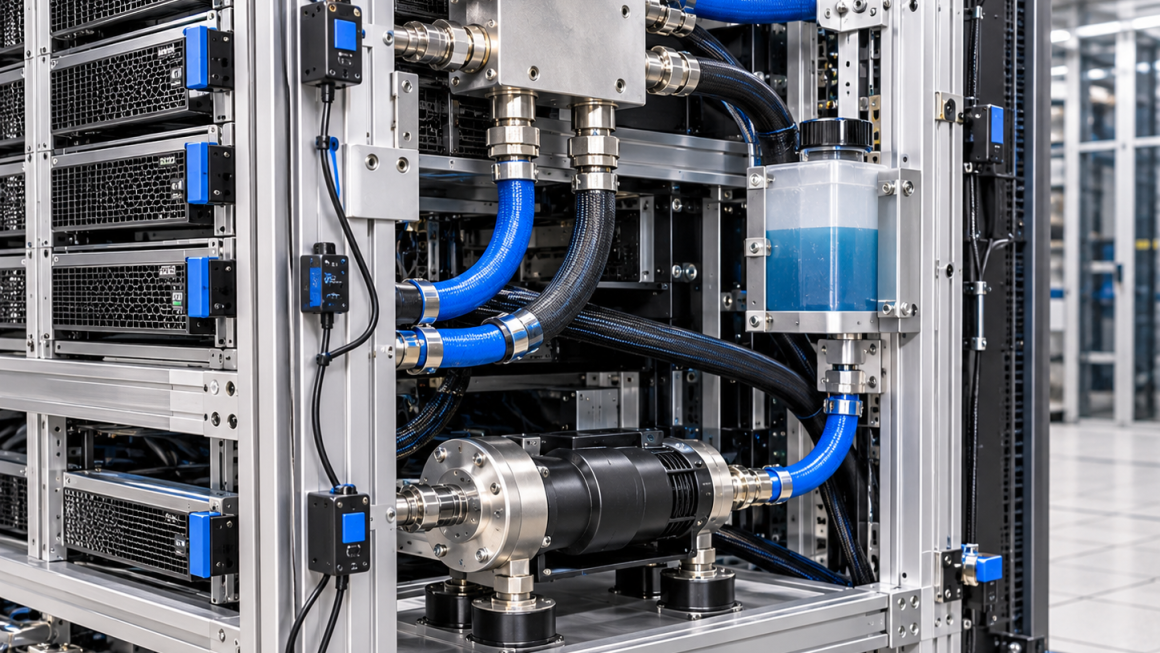
Liquid-cooled AI racks are becoming increasingly complex mechanical systems. In addition to supporting high-density GPU servers, power distribution equipment, and cooling manifolds, they must accommodate pumps, fans, coolant hoses, quick-disconnect fittings, and other fluid distribution components.
These systems introduce dynamic loads that can affect rack stability and long-term mechanical reliability.
Unlike a conventional server rack, a liquid-cooled AI rack contains multiple interconnected mechanical and fluid systems. Vibrations generated by cooling pumps, fans, server components, and external equipment can travel through the rack structure and affect mounting interfaces, hose connections, and sealing components.
A rack may satisfy its static load requirements but still experience excessive vibration, local resonance, connection loosening, or unwanted movement during operation.
This makes liquid-cooled AI rack vibration and stability an important consideration during structural design and system integration.
Aluminum extrusions, CNC-machined brackets, reinforced joints, and modular support structures can provide flexible solutions for liquid-cooled rack platforms. However, material selection alone cannot guarantee vibration resistance.
Reliable performance depends on structural stiffness, connection design, damping characteristics, equipment placement, hose routing, and appropriate mechanical validation.
This article examines the main engineering considerations involved in designing mechanically stable aluminum structures for liquid-cooled AI racks.
2. Understanding Vibration Sources in Liquid-Cooled AI Racks
Vibration in an AI rack can originate from several sources. Each source has different frequency characteristics, load paths, and potential effects on the structure.
2.1 Cooling Pump Vibration
Pumps are important sources of mechanical excitation in liquid cooling systems.
Depending on pump design and operating conditions, vibration may originate from:
- Rotating components
- Motor imbalance
- Bearing conditions
- Impeller interaction
- Hydraulic pulsation
- Flow instability
- Pump mounting interfaces
Pump vibration can be transmitted through its mounting brackets, connected pipes, coolant manifolds, and supporting rack structure.
If a pump is rigidly mounted to a relatively flexible aluminum frame, the frame may amplify certain vibration frequencies.
The mounting arrangement should therefore consider both pump support stiffness and vibration transmission.
Possible design measures include:
- Reinforced pump mounting plates
- Appropriately selected vibration isolation elements
- Short and mechanically stable mounting paths
- Controlled pipe and hose connections
- Adequate support around heavy pump assemblies
Vibration isolation should be selected according to the pump’s operating frequency, mass, mounting conditions, temperature, and fluid environment. An isolation element that is too soft may introduce excessive movement or create additional resonance problems.
2.2 Fan-Induced Vibration
Fans used in servers, power conversion equipment, and cooling systems can generate periodic mechanical excitation.
Potential sources include:
- Rotor imbalance
- Blade-pass excitation
- Motor vibration
- Bearing wear
- Fan speed variation
- Aerodynamic interaction
The frequency of fan-related vibration may change with operating speed.
In high-density AI racks, multiple fans may operate simultaneously, creating several excitation frequencies.
The structural design should consider whether these frequencies may interact with the natural modes of the rack, mounting brackets, or equipment support structures.
2.3 Server and Power Equipment Vibration
Other rack-mounted equipment can also introduce vibration.
Examples include:
- GPU server cooling fans
- Power supply modules
- Power conversion equipment
- Internal rotating components
- Mechanical switching or operating mechanisms
The combined effect of multiple sources may create a more complicated vibration environment than any individual component produces.
For this reason, rack-level vibration evaluation should consider the complete equipment configuration rather than relying exclusively on isolated component specifications.
2.4 External Vibration Sources
Liquid-cooled AI racks may also be exposed to vibration transmitted through the building floor, equipment foundations, cooling infrastructure, or adjacent machinery.
External excitation may be particularly relevant in facilities with large mechanical cooling systems, industrial pumps, or other rotating equipment.
The rack support and installation arrangement should therefore be considered as part of the overall vibration system.
3. Aluminum Rack Structure: Stiffness, Mass, and Mechanical Stability
Aluminum is widely used in AI rack structures because of its relatively low density, manufacturing flexibility, and ability to form complex extruded profiles.
However, its elastic modulus is lower than that of steel.
For structures with similar geometry, aluminum may therefore experience greater elastic deflection under the same loading conditions.
This does not mean aluminum is unsuitable for high-stability racks. It means that profile geometry, cross-sectional properties, joint design, and structural layout must be carefully considered.
3.1 Structural Stiffness and Deflection
A mechanically stable rack should limit unwanted movement under both static and dynamic loading.
Important design considerations include:
- Vertical frame stiffness
- Horizontal cross-member stiffness
- Resistance to lateral movement
- Torsional rigidity
- Local bracket deformation
- Joint stiffness
- Load distribution between structural members
Larger profile sections, reinforced corners, additional cross-members, and appropriately positioned braces can improve overall structural stiffness.
However, simply increasing the thickness of every aluminum profile is not always the most efficient solution.
A better approach is to identify the locations where structural deformation has the greatest influence on equipment alignment and vibration response.
3.2 Joint Design and Connection Stability
In modular aluminum racks, mechanical joints are often important sources of flexibility.
Bolted connections, corner brackets, T-slot fasteners, and mounting plates may introduce localized compliance.
Potential problems include:
- Fastener loosening
- Joint slip
- Localized deformation
- Fretting at contact interfaces
- Changes in connection stiffness
- Uneven load distribution
For vibration-sensitive applications, connection design should consider fastener preload, engagement length, contact area, and assembly consistency.
Where necessary, reinforced connectors or dedicated machined joint components can improve the rigidity of critical interfaces.
3.3 Cross-Bracing and Structural Geometry
Cross-bracing can help improve lateral stability, particularly in tall rack structures.
Depending on the rack configuration, engineers may use:
- Diagonal braces
- Rear structural panels
- Reinforced corner brackets
- Horizontal cross-members
- Integrated support plates
The most effective arrangement depends on the rack’s dimensions, equipment layout, installation constraints, and required access.
Structural improvements should be evaluated against the complete rack configuration to avoid creating unnecessary weight or restricting maintenance access.
4. Coolant Hose Mechanical Loads and Connection Reliability
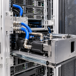
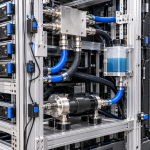
Coolant hoses are an important part of the mechanical system in liquid-cooled AI racks.
They transport coolant between cold plates, manifolds, pumps, distribution units, and external cooling infrastructure.
Although hoses are flexible, they can still transfer mechanical loads to the components they connect.
This is particularly important for quick-disconnect fittings and precision-machined aluminum manifolds.
4.1 Hose Weight and Support Requirements
Long or heavy coolant hoses can create sustained loads at connection points.
The resulting forces may depend on:
- Hose length
- Hose diameter
- Fluid mass
- Routing direction
- Support spacing
- Installation position
- Bending configuration
The rack structure should provide suitable hose support so that connectors do not become unintended structural support points.
Possible solutions include:
- Dedicated hose support brackets
- Adjustable routing guides
- Cable and hose management channels
- Soft-contact retaining clamps
- Reinforced manifold mounting interfaces
The support arrangement should prevent excessive sagging while allowing the movement required during installation and maintenance.
4.2 Bending Forces and Connector Loading
Hoses can exert forces on connected fittings when they are bent, twisted, stretched, or installed under tension.
These forces may create additional mechanical loading on:
- Quick-disconnect couplings
- Threaded manifold ports
- O-ring sealing interfaces
- Cold plate connections
- Pump inlet and outlet fittings
A hose that is too short may pull on a connector, while an excessively long hose may create unnecessary weight, bending, or interference.
The routing design should follow the hose manufacturer’s minimum bend-radius requirements and account for the actual movement expected during operation.
4.3 Vibration Transmission Through Coolant Lines
A hose can transmit vibration between two mechanically connected components.
For example, vibration from a pump may travel through a coolant line and reach a manifold mounted on another part of the rack.
Conversely, movement of the rack may transfer mechanical loads back to the pump or external cooling connections.
Flexible connections can help accommodate relative movement, but their effectiveness depends on hose construction, length, routing, support conditions, and operating pressure.
The design should avoid unnecessary rigid connections that create unintended vibration transmission paths.
4.4 Quick-Disconnect Fittings and Sealing Interfaces
Quick-disconnect fittings simplify maintenance and component replacement, but they also introduce mechanical interfaces that require careful support.
Important considerations include:
- Connector alignment
- Insertion and removal forces
- Hose-induced bending loads
- Axial loading
- Vibration exposure
- Seal compatibility
- Repeated connection cycles
The fitting should not be expected to compensate for poor hose routing or excessive structural movement.
Where appropriate, the hose and manifold should be independently supported to reduce unnecessary loads on the coupling.
5. Structural Modes and Resonance in AI Racks
One of the most important aspects of vibration engineering is understanding the natural frequencies and mode shapes of a structure.
Every mechanical structure has natural vibration characteristics determined by its mass, stiffness, geometry, and boundary conditions.
When an external excitation frequency approaches a structural natural frequency, resonance may occur.
This can increase vibration amplitude and mechanical stress.
5.1 Natural Frequency
The natural frequency of a simplified mechanical system can be expressed as:
[
f_n=\frac{1}{2\pi}\sqrt{\frac{k}{m}}
]
Where:
- (f_n) = natural frequency
- (k) = equivalent stiffness
- (m) = equivalent mass
This simplified relationship illustrates an important design principle.
Increasing stiffness generally raises natural frequency, while increasing mass generally lowers it.
However, a real AI rack is a multi-degree-of-freedom structure with multiple natural frequencies and complex mode shapes.
A single-frequency calculation cannot fully describe its dynamic behavior.
5.2 Understanding Structural Mode Shapes
A mode shape describes how different parts of a structure move during a particular vibration mode.
For an aluminum AI rack, relevant modes may include:
- Lateral bending of the complete rack
- Front-to-rear structural movement
- Torsional deformation
- Local vibration of horizontal rails
- Flexible response of equipment mounting brackets
- Vibration of pump support assemblies
- Local deformation of manifold mounting structures
Understanding these modes helps engineers identify where reinforcement or changes in equipment placement may be beneficial.
5.3 Avoiding Resonance with Operating Frequencies
Pump speeds, fan speeds, and other rotating equipment may produce excitation frequencies that vary during operation.
The structural design should consider the expected operating frequency ranges rather than evaluating only one nominal operating point.
Potential solutions include:
- Increasing local structural stiffness
- Adjusting equipment mounting positions
- Changing bracket geometry
- Improving support conditions
- Introducing suitable damping
- Modifying equipment operating ranges where system requirements allow
The objective is not simply to make every structure as rigid as possible.
It is to achieve an acceptable dynamic response across the intended operating conditions.
6. Vibration Isolation and Damping Strategies
Vibration isolation and damping can help reduce the transmission or amplification of dynamic loads.
However, these are different engineering concepts.
Vibration isolation aims to reduce the transmission of vibration between connected systems.
Damping helps dissipate vibrational energy and reduce response amplitude.
Both may be useful in liquid-cooled AI rack design.
6.1 Pump Mounting Isolation
Depending on the pump design and operating conditions, isolation elements may be installed between the pump and its supporting structure.
The selected element should consider:
- Pump mass
- Operating speed
- Excitation frequency
- Static deflection
- Temperature
- Coolant exposure
- Long-term aging
- Required positional stability
An incorrectly selected isolator may worsen vibration near its resonance region or permit excessive movement.
6.2 Local Damping and Reinforcement
Damping materials or specially designed structural interfaces may be used to reduce localized vibration.
Possible applications include:
- Pump mounting assemblies
- Equipment support brackets
- Panel interfaces
- Cable and hose contact points
- Selected structural connections
The material must be compatible with the operating environment and should not compromise mechanical load capacity or maintenance requirements.
6.3 Avoiding Uncontrolled Flexible Connections
Adding flexible elements does not automatically improve vibration performance.
An excessively flexible mounting arrangement may create large movements, additional resonance modes, or alignment problems.
Isolation elements, flexible hoses, and support brackets should therefore be evaluated as part of the complete mechanical system.
7. Designing Stable Mounting Interfaces for Liquid Cooling Components
The mechanical interfaces between the aluminum rack and liquid cooling equipment are particularly important.
A pump, manifold, coolant distribution unit, or hose support may introduce concentrated loads into the frame.
7.1 Pump and Cooling Unit Mounting
Pump assemblies and cooling units should be mounted through interfaces capable of supporting their weight and dynamic loading.
Possible structural solutions include:
- Reinforced aluminum mounting plates
- Cross-member support structures
- CNC-machined mounting brackets
- Integrated extrusion slots
- Dedicated vibration isolation interfaces
The mounting arrangement should also allow appropriate service access.
7.2 Manifold Support
Liquid cooling manifolds may contain multiple hose or pipe connections.
Their support design should prevent the combined weight and mechanical forces of connected hoses from creating excessive bending loads at the manifold ports.
For larger assemblies, multiple mounting points may be needed to control rotation and local deformation.
7.3 Cold Plate and Server Integration
Although cold plates are generally mounted within server assemblies rather than directly to the rack, rack vibration can influence the connected system through chassis mounting interfaces and external coolant lines.
The mechanical design should therefore consider how rack movement interacts with server chassis, hose connections, and manifold assemblies.
The objective is to prevent unnecessary relative movement from being transferred into sensitive fluid connections.
8. Aluminum Manufacturing Considerations for Vibration-Resistant Racks
The manufacturing process has a direct influence on the consistency of the final structure.
Custom aluminum extrusions and CNC-machined components can be combined to produce rack assemblies with controlled mechanical interfaces.
8.1 Custom Aluminum Extrusions
Extruded profiles can integrate structural features such as:
- Reinforced mounting channels
- T-slots
- Internal ribs
- Multiple fastening interfaces
- Cable and hose routing features
- Modular connection geometry
Profile geometry should be selected according to the required bending and torsional stiffness, rather than relying on external dimensions alone.
8.2 CNC-Machined Structural Brackets
CNC machining can produce precision interfaces for:
- Pump mounting plates
- Manifold support brackets
- Reinforced corner connectors
- Equipment mounting adapters
- Cross-member connections
These components can help improve alignment and connection repeatability.
8.3 Welding and Mechanical Assembly
Depending on the rack design, structural components may be connected through bolting, welding, or hybrid assembly methods.
Each approach has different implications for stiffness, dimensional accuracy, residual stress, and maintenance.
For modular rack systems, bolted connections may offer easier replacement and reconfiguration.
For permanently integrated structures, welding may be appropriate when the design and material condition support it.
The complete assembly should be validated after manufacturing because individual component performance does not necessarily predict overall rack stability.
9. Aluminum Rack Vibration Testing and Mechanical Validation
Vibration testing is an important part of validating liquid-cooled AI rack structures.
The testing strategy should reflect the actual equipment configuration, installation conditions, and intended operating environment.
A practical validation program may include several stages.
9.1 Modal Analysis
Modal analysis identifies the natural frequencies and mode shapes of a structure.
It may be performed through finite element analysis (FEA), experimental modal testing, or a combination of both.
For AI rack structures, modal analysis can help identify:
- Low-frequency global bending modes
- Torsional modes
- Local bracket resonance
- Flexible equipment support structures
- Potential interaction with pump and fan excitation
FEA results should be based on realistic material properties, joint stiffness, equipment mass, and boundary conditions.
9.2 Experimental Modal Testing
Experimental modal testing uses controlled excitation and measurement equipment to characterize the actual structure.
Typical equipment may include:
- Impact hammers
- Electrodynamic shakers
- Accelerometers
- Data acquisition systems
- Signal analysis software
Measurements can be taken at selected locations on the rack frame, equipment brackets, pump supports, and other critical interfaces.
This helps verify whether the manufactured assembly behaves as expected.
9.3 Operational Vibration Measurement
Operational testing evaluates vibration while the rack operates under representative conditions.
Testing may include different pump and fan speeds, equipment configurations, and coolant operating states.
Measurement locations may include:
- Main rack frame
- Pump mounting points
- Manifold supports
- Server mounting rails
- Hose support brackets
- Selected connector interfaces
The measured vibration should be evaluated against the equipment manufacturer’s limits and the project’s agreed acceptance requirements.
9.4 Shaker Testing
A vibration shaker can apply controlled mechanical excitation to an assembly.
Depending on the application, testing may involve:
- Sinusoidal vibration
- Random vibration
- Frequency sweeps
- Defined vibration profiles
- Resonance investigation
The test profile should be based on the expected operating or transportation environment.
A generic vibration profile should not be applied without confirming that it represents the intended use case.
9.5 Post-Test Inspection
After vibration testing, critical mechanical and fluid interfaces should be inspected.
Relevant checks include:
- Fastener retention
- Joint movement
- Bracket deformation
- Structural cracks
- Hose abrasion
- Connector alignment
- Seal condition
- Evidence of coolant leakage
Where appropriate, pressure and leak testing should be repeated after vibration exposure to evaluate whether the mechanical test has affected the integrity of the coolant system.
10. Integrated Validation: Testing the Rack as a Complete System
Testing individual aluminum profiles or brackets is not sufficient to establish the vibration performance of a complete liquid-cooled AI rack.
The final system contains multiple interacting components, each with its own mass, stiffness, and excitation characteristics.
An integrated validation plan may include:
| Validation area | Main evaluation objectives |
|---|---|
| Static structural loading | Load capacity, deflection, connection stability |
| Modal analysis | Natural frequencies and mode shapes |
| Operational vibration | Response under actual pump and fan operation |
| Pump isolation | Vibration transmission through mounting interfaces |
| Hose support | Routing stability and mechanical load distribution |
| Connector inspection | Alignment, retention, and visible damage |
| Pressure and leak testing | Coolant circuit integrity before and after testing |
| Thermal operation | Structural behavior under operating temperatures |
| Maintenance simulation | Movement and loading during servicing |
The acceptance criteria should be defined according to the application, equipment specifications, customer requirements, and relevant standards.
For example, an acceptable vibration level at the main rack frame does not automatically mean that a quick-disconnect fitting experiences acceptable mechanical loading.
Critical components may require separate measurement or inspection.
11. Practical Design Checklist for Liquid-Cooled AI Rack Stability
Before finalizing a rack structure, engineers should review the following areas.
Structural Design
- Main frame stiffness
- Cross-member placement
- Torsional stability
- Local bracket stiffness
- Joint design and fastener retention
Dynamic Loads
- Pump operating frequencies
- Fan operating frequencies
- Equipment vibration characteristics
- External vibration conditions
- Potential resonance interactions
Coolant Hose Management
- Hose weight and support
- Minimum bend radius
- Connector alignment
- Relative movement between connected components
- Abrasion and interference prevention
Mounting Interfaces
- Pump mounting stiffness
- Manifold support
- Server mounting interfaces
- Vibration isolation requirements
- Maintenance accessibility
Validation
- Structural analysis
- Modal analysis
- Operational vibration measurement
- Vibration testing where required
- Post-test inspection
- Pressure and leak verification
Addressing these factors during the design stage can reduce the risk of mechanical problems emerging after the rack has been installed in a data center.
12.
Mechanical stability is an essential design requirement for liquid-cooled AI racks.
Pumps, fans, servers, power equipment, and external cooling infrastructure can introduce dynamic loads that influence the rack frame, equipment mounting interfaces, and coolant connections.
For aluminum rack structures, reliable performance depends on more than static load capacity. Engineers must also consider structural stiffness, joint behavior, natural frequencies, resonance, damping, and vibration transmission.
Coolant hoses deserve particular attention because their weight, routing, bending forces, and relative movement can introduce additional loads on quick-disconnect fittings and manifold connections.
A combination of structural analysis, appropriate mounting design, hose support, vibration measurement, and integrated validation can help improve long-term system reliability.
At Aluminum4AI, we support custom aluminum extrusions, CNC-machined brackets, structural frames, equipment mounting components, and mechanical integration solutions for AI infrastructure.
By considering dynamic loads and fluid connection requirements from the beginning of the design process, manufacturers can develop more stable and serviceable aluminum structures for next-generation liquid-cooled AI racks.