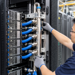
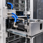
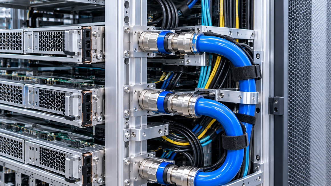
As AI servers become more powerful and GPU rack densities continue to increase, liquid cooling systems are becoming an important part of modern data center infrastructure. Flexible coolant hoses connect cold plates, distribution manifolds, rack-level cooling interfaces, and other components throughout the system.
However, designing a reliable liquid cooling system involves more than selecting hoses with the correct pressure rating and fluid compatibility. How these hoses are routed inside the server and across the rack can directly affect mechanical reliability, maintenance access, and long-term operating stability.
Poor hose routing may introduce excessive bending, torsional stress, vibration, or interference with electrical cables. It can also make server replacement more difficult and transfer unnecessary mechanical loads to fittings and quick-disconnect connectors.
For AI infrastructure manufacturers, hose routing should therefore be treated as an integrated mechanical design task involving aluminum structures, cooling components, cable management, and equipment serviceability.
This article examines the key engineering considerations for AI liquid cooling hose routing design, with particular attention to bend radius, torsion, dynamic movement, support points, thermal expansion, and cable interference.
1. Why Hose Routing Design Matters in Liquid-Cooled AI Servers
In a liquid-cooled AI server, coolant hoses may connect:
- GPU cold plates
- CPU cold plates
- Rack-level coolant distribution manifolds
- Server-level distribution blocks
- Quick-disconnect connectors
- Internal cooling modules
These connections must accommodate the physical arrangement of components while maintaining a suitable coolant flow path.
Unlike rigid pipes, flexible hoses can adapt to different layouts and allow equipment to be installed or removed more easily. However, their flexibility also introduces additional design considerations.
A poorly routed hose may experience:
- Bending below its specified minimum radius
- Twisting during installation or maintenance
- Repeated movement near fittings
- Compression or pinching against structural components
- Contact with sharp edges
- Interference with power and data cables
- Unnecessary loading on connectors and manifolds
These problems may not be immediately visible during initial assembly. Some only become apparent after repeated server replacement, thermal cycling, or long-term operation.
A well-designed hose routing system should maintain the required flow path while minimizing mechanical stress and preserving maintenance access.
2. Coolant Hose Bend Radius: Avoiding Excessive Curvature
Bend radius is one of the most important parameters in liquid cooling hose installation.
Every hose has a specified minimum bend radius, generally provided by its manufacturer. This value depends on hose construction, internal diameter, reinforcement, material, pressure rating, and operating conditions.
When a hose is bent below its permitted radius, several problems may occur:
- Local deformation of the hose wall
- Reduction in effective internal flow area
- Increased flow resistance
- Uneven mechanical stress across the hose structure
- Premature wear or damage under repeated movement
In severe cases, excessive bending may cause kinking or partial blockage.
Static and dynamic bend radius
Engineers should distinguish between two different operating conditions.
Static bend radius
This applies when a hose remains in a fixed position after installation. The hose does not undergo significant repeated movement during normal operation.
Dynamic bend radius
This applies when a hose moves repeatedly, such as during server insertion, extraction, or adjustment of a movable cooling module.
A hose that meets the minimum bend radius in a stationary installation may not be suitable for the same routing arrangement when repeated movement is required.
Dynamic applications should be evaluated using the hose manufacturer’s specific requirements for movement, fatigue, and service life.
Practical design considerations
When routing coolant hoses inside an AI server or GPU rack:
- Maintain the manufacturer’s specified minimum bend radius.
- Avoid sharp turns immediately next to fittings.
- Allow sufficient space for gradual transitions.
- Check the hose shape after all covers and panels are installed.
- Consider the full movement envelope of removable equipment.
- Avoid forcing a hose into position during final assembly.
The minimum bend radius should be treated as a design constraint, not a target that every installation must approach as closely as possible.
3. Torsion Control: Why Twisting Is Different from Bending
Hose bending and hose twisting are not the same mechanical condition.
Bending changes the direction of a hose along its length. Torsion occurs when the hose is rotated around its longitudinal axis.
Torsional loading can be introduced when:
- A hose is installed with its ends misaligned.
- The hose is rotated to connect a fitting.
- The routing path forces the hose to turn while its ends are fixed.
- A server is moved without sufficient hose flexibility.
- Installation personnel compensate for insufficient clearance by twisting the hose.
Excessive torsion can place additional stress on the hose reinforcement, connection interfaces, and sealing components.
It may also cause the hose to move away from its intended routing position during operation.
How to reduce torsional stress
A practical design approach includes:
Align connection points
Position fittings and connection interfaces so the hose can follow a natural path without requiring forced rotation.
Use appropriate hose orientation
Check the manufacturer’s installation instructions and any directional or orientation requirements.
Avoid twisting during assembly
Where necessary, use alignment marks or visual references to confirm that the hose is not twisted before final fastening.
Allow controlled movement
For removable servers, provide sufficient hose length and routing clearance to accommodate the intended movement without introducing torsional loads.
The objective is to ensure that the hose follows its intended path without being forced into an unstable mechanical position.
4. Dynamic Movement: Designing for Server Installation and Removal
One of the most challenging aspects of hose routing in high-density AI racks is accommodating equipment movement.
Many GPU servers are installed on sliding rails or removable mounting systems. During maintenance, a server may need to be partially or fully extracted from the rack.
If coolant hoses are connected directly to fixed rack-level manifolds, the routing arrangement must accommodate the movement of the server without excessive pulling, bending, or twisting.
This creates a dynamic design problem.
Movement-related design risks
Common problems include:
- Hoses becoming stretched during server extraction
- Connectors receiving unintended pulling forces
- Hoses bending sharply near the rack interface
- Interference with neighboring servers
- Hoses becoming trapped between sliding components
- Insufficient clearance for reconnection
A hose layout that appears acceptable when the server is fully installed may become problematic when the server is moved forward.
Designing the movement envelope
Engineers should evaluate the hose path in multiple equipment positions:
- Fully installed operating position
- Initial service position
- Partially extracted position
- Fully accessible maintenance position
- Reinstallation and reconnection position
The hose should maintain acceptable curvature and mechanical loading throughout the intended movement range.
Where repeated movement is expected, the design may require additional flexibility, dedicated hose guides, or a service loop.
However, simply adding more hose length is not always the best solution. Excessive slack can create tangling, obstruction, and unwanted contact with other components.
The correct approach is to design a controlled movement path based on the actual server travel distance and hose specifications.
5. Fixed Points and Hose Supports: Controlling the Routing Path
Hose support points help maintain an organized routing layout and reduce unnecessary movement.
In an AI rack, supports may be integrated into:
- Aluminum extrusion profiles
- CNC-machined mounting brackets
- Rack-side cable and hose management rails
- Server chassis brackets
- Manifold support structures
The location of each support point is important.
Too few supports may allow the hose to sag, vibrate, or contact nearby components. Too many rigidly fixed points may restrict movement and introduce stress when the hose expands or the server is removed.
Fixed points versus guided supports
A useful design distinction is between fixed points and guided supports.
Fixed points
These establish a defined position for a hose section. They may be used near a manifold or at a stable structural interface.
Guided supports
These control the general routing path while allowing a degree of movement where required.
For flexible hose systems, not every support should necessarily prevent movement. Some sections need controlled freedom to accommodate thermal expansion, vibration, or equipment servicing.
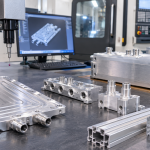
Aluminum support structures
Aluminum extrusions can provide adjustable mounting positions for hose clamps and routing brackets.
CNC-machined aluminum plates can be used where more precise mounting geometry is required.
When selecting or designing hose supports, engineers should consider:
- Hose diameter and external dimensions
- Clamp material and contact surface
- Local support stiffness
- Fastener retention
- Vibration resistance
- Allowable hose movement
- Protection against abrasion
Clamps should hold the hose securely without excessive compression or deformation. The appropriate clamping method should be compatible with the hose manufacturer’s installation recommendations.
6. Thermal Expansion and Temperature-Related Movement
Liquid cooling systems operate under changing temperatures. Coolant temperature, server component temperature, and surrounding air temperature may vary during startup, shutdown, and changes in computing load.
These temperature changes can affect the dimensions and mechanical behavior of the cooling assembly.
Although flexible hoses can accommodate some movement, their routing must still account for thermal effects.
Potential issues include:
- Changes in hose flexibility
- Dimensional movement of connected components
- Expansion or contraction of aluminum structures
- Relative movement between manifolds and server chassis
- Changes in hose tension or support loading
Aluminum has a relatively high coefficient of thermal expansion compared with many other structural materials. Therefore, the relative movement between aluminum mounting structures, rigid manifolds, and connected components should be considered.
Managing thermal movement
A practical design may include:
- Flexible hose sections at appropriate interfaces
- Routing paths that avoid unnecessary restraint
- Support arrangements that allow controlled movement
- Adequate clearance around nearby components
- Compatibility between hose materials and operating temperatures
Engineers should avoid fixing every hose section rigidly between two components that may move differently as temperatures change.
The objective is to prevent thermal movement from being transferred as excessive tension, compression, or bending stress to the hose connections.
7. Preventing Interference Between Coolant Hoses and Electrical Cables
High-density AI servers contain multiple systems that compete for limited internal space.
These may include:
- High-current power cables
- High-speed data and signal cables
- Sensor wiring
- Fan and control cables
- Coolant supply and return hoses
If routing is not carefully coordinated, coolant hoses may interfere with electrical cables or other hardware.
Potential problems include:
- Hoses pressing against cable bundles
- Cables restricting the required hose bend radius
- Abrasion caused by repeated contact
- Obstructed airflow in air-cooled sections
- Reduced access to connectors and service components
- Cable movement affecting hose stability
Establishing routing zones
A practical approach is to define routing zones during the mechanical design stage.
For example:
Coolant routing zone
Allocate a defined space for supply and return hoses, including their bending and movement envelopes.
Power cable zone
Keep high-current power cables organized and prevent coolant hoses from pressing against connectors or cable terminations.
Data and signal cable zone
Provide controlled routing paths for communication and sensor wiring, avoiding unnecessary crossings and mechanical contact.
Maintenance access zone
Preserve sufficient space for technicians to disconnect hoses, remove servers, and access electrical interfaces.
The exact separation requirements depend on the electrical system, hose construction, insulation, cooling architecture, and applicable safety standards. Engineers should verify these requirements for the specific system rather than assuming a universal separation distance.
8. Integrating Hose Management with Aluminum AI Rack Structures
Aluminum structures can play an important role in organizing liquid cooling hoses.
Rather than treating hose routing as an independent plumbing task, manufacturers can integrate hose management features directly into the rack architecture.
Possible solutions include:
Extruded aluminum profiles
Custom extrusions can provide mounting slots and defined support locations for hose guides, clamps, and cable management accessories.
CNC-machined brackets
Machined brackets can provide precise interfaces for hose supports, manifolds, and connector mounting plates.
Adjustable mounting rails
Modular rails allow hose support positions to be modified as the cooling configuration changes.
Protective edge features
Rounded edges, covers, and protective inserts can help reduce abrasion where hoses pass near aluminum structures.
Integrated cable and hose management
Dedicated channels and support brackets can help organize different routing systems while maintaining service access.
A hybrid manufacturing approach can be particularly effective. Extrusions provide the main structural framework, while CNC-machined components deliver application-specific mounting features.
This approach supports modularity without requiring every rack configuration to use a completely different structural design.
9. Testing and Validation of Hose Routing Designs
A hose routing arrangement should be evaluated as a complete mechanical and fluid system.
A visual inspection alone is not sufficient to confirm that the hose will perform reliably throughout its intended service life.
A practical validation program may include:
| Validation item | Main purpose |
|---|---|
| Bend radius inspection | Confirm compliance with hose specifications |
| Torsion inspection | Identify unwanted hose rotation |
| Movement simulation | Check hose behavior during server extraction |
| Support evaluation | Verify clamp retention and structural stability |
| Thermal cycling | Evaluate movement under temperature changes |
| Vibration testing | Assess hose contact, wear, and support stability |
| Pressure and leak testing | Verify fluid-system integrity |
| Maintenance simulation | Confirm access and reconnection procedures |
| Cable interference review | Identify contact and routing conflicts |
For dynamic hose arrangements, testing should include repeated movement through the intended service range.
Pressure and leak testing should follow the approved procedure for the complete cooling assembly. Testing should also account for the actual connector, hose, fitting, and operating conditions.
10. Common Hose Routing Mistakes in AI Liquid Cooling Systems
Several recurring design problems can be avoided through early coordination between mechanical, thermal, and electrical engineering teams.
1. Using the minimum bend radius as the normal routing target
This leaves little tolerance for assembly variation or dynamic movement.
2. Ignoring torsion during installation
The hose may appear correctly positioned while retaining unwanted rotational stress.
3. Designing only for the installed server position
The routing may fail when the server is pulled forward for maintenance.
4. Fixing every hose section rigidly
Excessive restraint can prevent the system from accommodating thermal or mechanical movement.
5. Allowing hoses to carry connector loads
Hose weight and movement should not unnecessarily load QD connectors or manifold interfaces.
6. Routing hoses through cable management space
This can create interference, abrasion, and maintenance difficulties.
7. Adding excessive hose slack
Uncontrolled loops may obstruct airflow, access, or neighboring equipment.
A successful design balances flexibility, structural support, compactness, and serviceability.
11. From Prototype to Production: A Practical Design Workflow
For manufacturers developing custom liquid-cooled AI servers and racks, hose routing should be included in the design verification process from the beginning.
A structured workflow can help reduce redesign and assembly problems.
Step 1: Identify all cooling interfaces
Define the cold plates, manifolds, QD connectors, hose specifications, and supply and return paths.
Step 2: Define static and dynamic requirements
Determine which hoses remain stationary and which must accommodate server or module movement.
Step 3: Establish routing envelopes
Define the required bend radius, clearance, support locations, and movement space using actual component specifications.
Step 4: Coordinate with electrical routing
Review power cables, data cables, sensors, and maintenance access zones together with the coolant layout.
Step 5: Design aluminum support components
Develop extrusion profiles, mounting rails, brackets, and protective features to organize the hose path.
Step 6: Build a representative prototype
Install actual hoses, connectors, servers, and adjacent cable assemblies to evaluate the complete arrangement.
Step 7: Conduct mechanical and fluid validation
Verify movement, support stability, bend radius, pressure integrity, and maintenance procedures.
Step 8: Standardize the production layout
Document routing paths, clamp locations, installation sequence, and inspection requirements for consistent assembly.
This process helps transform a workable prototype into a repeatable manufacturing solution.
AI liquid cooling hose routing design is an important part of reliable server and rack engineering. Bend radius, torsion, dynamic movement, support locations, thermal expansion, and cable interference all influence how the cooling system performs during operation and maintenance.
Flexible hoses provide valuable installation flexibility, but they still require carefully controlled routing and mechanical support.
Aluminum extrusion profiles, CNC-machined brackets, and modular mounting rails can help create organized hose management systems that accommodate both cooling requirements and equipment serviceability.
For AI infrastructure manufacturers, the goal is not simply to fit coolant hoses into the available space. It is to create a routing architecture that maintains the required flow path, protects mechanical connections, supports repeated maintenance, and remains practical to manufacture at scale.