

As liquid cooling systems become increasingly important in AI servers, high-performance computing, and data center infrastructure, the reliability of aluminum cooling components has become a critical engineering requirement.
CNC-machined aluminum cold plates, manifolds, cooling blocks, and fluid distribution components must withstand operating pressure while maintaining reliable sealing performance throughout their service life.
A component that appears dimensionally accurate and visually sound may still contain internal machining defects, sealing surface imperfections, or assembly-related leakage paths. These issues may not become apparent until the component is exposed to pressure or connected to a complete cooling circuit.
This is why aluminum cold plate pressure and leak testing should be treated as essential validation steps rather than optional final inspections.
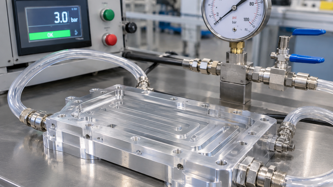
However, pressure testing and leak testing are not the same procedure. Pressure testing evaluates the component’s ability to withstand a specified pressure condition, while leak testing focuses on identifying or quantifying fluid or gas escaping from the pressure boundary.
Understanding the distinction helps manufacturers establish a more reliable validation process for CNC-machined aluminum cooling components.
2. Pressure Testing vs. Leak Testing: Understanding the Difference
Although these procedures are frequently performed together, they address different failure modes.
Pressure Testing: Evaluating Structural Integrity
Pressure testing verifies whether a component can withstand a defined internal pressure without unacceptable deformation, structural damage, or failure.
For aluminum cold plates and manifolds, the test may help identify:
- Weak areas in thin channel walls
- Structural defects around internal passages
- Insufficient material thickness
- Potential failure around threaded ports
- Deformation of covers or sealing interfaces
- Defects associated with machining or joining processes
The test pressure, duration, test medium, and acceptance requirements must be established according to the component design, specified operating conditions, customer requirements, and applicable standards.
A pressure test does not automatically demonstrate that a component is leak-tight under every operating condition.
Leak Testing: Evaluating Sealing Performance
Leak testing determines whether coolant or test gas can escape through the component’s pressure boundary.
Typical leakage paths include:
- O-ring sealing interfaces
- Threaded connections
- Gasket joints
- Brazed or welded seams
- Machined channel boundaries
- Porosity or defects in the aluminum material
- Connections between the cold plate body and manifold cover
Leak testing may use liquid-based inspection, pressure decay, gas pressure methods, or other suitable techniques depending on the required sensitivity and component design.
The appropriate method should reflect the intended coolant, operating environment, acceptable leakage rate, and downstream system requirements.
The key distinction: Pressure testing evaluates pressure resistance; leak testing evaluates sealing integrity. A reliable validation program may require both.
3. Common Pressure and Leak Testing Methods
Different testing methods offer different levels of sensitivity, complexity, and risk. The choice should be based on the component’s design and validation requirements.
3.1 Hydrostatic Pressure Testing
Hydrostatic testing uses a liquid, typically water or another compatible test medium, to pressurize the component.
The component is filled with liquid, trapped air is removed as far as practical, and pressure is increased under controlled conditions.
Potential advantages include:
- Lower stored energy compared with compressed-gas testing
- Practical inspection for visible liquid leakage
- Suitability for many machined cooling components
- Relatively straightforward test equipment
Important considerations include:
- Test-medium compatibility with aluminum and other wetted materials
- Water quality and contamination control
- Complete drainage after testing
- Drying requirements for internal cooling channels
- Prevention of corrosion during storage or shipment
For precision liquid cooling components, residual water or moisture can create contamination and corrosion concerns if the component is not properly dried and protected.
3.2 Pneumatic Pressure Testing
Pneumatic testing uses compressed gas, such as air or nitrogen, to pressurize the component.
It may be useful when liquid contamination must be avoided or when the component’s internal passages are difficult to dry.
However, compressed gas stores significantly more energy than an equivalent volume of liquid under pressure. A failure can therefore release substantial energy.
Pneumatic testing requires appropriate risk assessment, controlled pressurization, suitable protective measures, and qualified operating procedures.
It should not be treated as a simple substitute for hydrostatic testing.
3.3 Pressure Decay Testing
Pressure decay testing monitors the reduction in pressure inside a sealed component over a defined period.
After the component reaches the specified test pressure and stabilizes, the pressure change is recorded.
This method can support repeatable production inspection, particularly when test fixtures and environmental conditions are carefully controlled.
However, pressure decay can be affected by:
- Temperature changes
- Internal volume
- Fixture leakage
- Seal relaxation
- Material deformation
- Gas permeability
- Instrument resolution
A pressure decrease does not necessarily indicate a component leak unless these factors are properly controlled.
3.4 Tracer Gas and Other Sensitive Leak Detection Methods
For applications requiring higher leak-detection sensitivity, manufacturers may consider tracer-gas methods or specialized leak detection equipment.
These approaches can help identify small leakage paths that may not be easily detected through conventional visual inspection.
Method selection should consider the required detection limit, component geometry, test cost, production volume, and customer acceptance criteria.
Not every cooling component requires the same level of leak-detection sensitivity.
4. Critical Design Areas That Affect Test Results
A reliable test process begins with a component designed for manufacturability and sealing performance.
4.1 Internal Channel Geometry and Wall Thickness
CNC-machined cold plates often contain complex internal channels designed to distribute coolant across thermal interfaces.
During machining, the remaining wall thickness between adjacent channels and between channels and external surfaces must be controlled.
Potential concerns include:
- Excessively thin channel walls
- Localized stress concentrations
- Tool marks or machining defects
- Insufficient material around threaded ports
- Variations in channel depth
- Internal passages approaching external surfaces
These conditions can affect both pressure resistance and leak performance.
Manufacturers should review the component drawing and machining process to identify critical pressure-boundary areas before production validation.
4.2 O-Ring Grooves and Sealing Surfaces
O-ring seals are commonly used in aluminum cold plates and manifolds.
Their performance depends on several interacting factors:
- Groove width and depth
- O-ring cross-sectional dimensions
- Compression and gland fill
- Surface finish
- Flatness of mating surfaces
- Fastener spacing and tightening sequence
- Elastomer compatibility with the coolant
- Operating temperature and pressure
A component may pass an initial test but develop leakage after repeated assembly, thermal cycling, or prolonged exposure to coolant.
For this reason, the sealing design should be evaluated against the intended operating environment rather than relying exclusively on a single initial test.
4.3 Threaded Ports and Fitting Interfaces
Threaded ports are another common source of leakage in CNC manifolds and cold plates.
Potential failure factors include:
- Incorrect thread specifications
- Damaged threads
- Insufficient engagement
- Excessive tightening torque
- Inappropriate sealing compounds
- Incompatible fitting materials
- Misalignment between the fitting and port
The test fixture should use compatible fittings and sealing arrangements that do not introduce artificial leakage paths.
Where possible, the production-representative connection configuration should be used during validation.
5. Test Setup: What Should Be Controlled?
The reliability of test results depends not only on the testing equipment but also on the consistency of the setup.
A well-defined test procedure should specify the following parameters.
5.1 Test Pressure
The test pressure must be determined from the component’s design pressure, intended operating conditions, applicable standards, and customer requirements.
Manufacturers should distinguish between:
- Normal operating pressure
- Maximum allowable operating pressure
- Design pressure
- Proof or qualification test pressure
- Burst pressure, where applicable
These values serve different engineering purposes and should not be used interchangeably.
A test pressure should never be selected simply by applying an arbitrary multiplier to the operating pressure without considering the governing design basis.
5.2 Test Medium
The test medium should be compatible with the aluminum alloy, seals, fittings, and any other materials exposed during testing.
Depending on the procedure, the medium may be:
- Deionized or otherwise controlled water
- A specified coolant mixture
- Dry air
- Nitrogen
- A designated tracer gas
If water is used, the test procedure should define water quality, exposure time, drainage, and drying requirements.
5.3 Pressure Ramp and Stabilization
Pressure should be increased according to a controlled procedure.
Rapid pressurization may create unnecessary mechanical stress or unstable test conditions.
A defined stabilization period helps reduce the influence of temperature changes, fixture behavior, and initial material response.
The procedure should also specify the pressure-holding duration and how readings are recorded.
5.4 Test Equipment and Calibration
Test equipment should have a measurement range and resolution suitable for the required test conditions.
Relevant equipment may include:
- Pressure gauges or digital pressure transducers
- Pressure regulators
- Isolation valves
- Test pumps
- Leak detection instruments
- Temperature sensors
- Dedicated test fixtures
Calibration status and equipment identification should be traceable in the inspection record.
For production testing, fixture repeatability is particularly important because inconsistent fixtures can create false failures or conceal actual component defects.
6. How to Validate CNC Aluminum Manifolds
A CNC manifold may contain multiple channels, ports, threaded connections, and sealing interfaces. Testing should therefore cover the complete pressure boundary rather than focusing on only one connection.
A typical validation workflow may include the following stages.
Step 1: Visual and Dimensional Inspection
Check the component for machining damage, burrs, visible cracks, surface defects, and dimensional deviations.
Pay particular attention to sealing faces, threaded ports, and thin-wall sections.
Step 2: Cleaning and Preparation
Remove machining chips, cutting fluid, and other contaminants from internal passages.
Ensure that the component is prepared according to the selected test method.
Step 3: Fixture Installation
Install compatible plugs, fittings, seals, and test connections.
Confirm that the fixture itself has been verified and that its sealing arrangement will not compromise the test.
Step 4: Controlled Pressurization
Increase pressure according to the approved procedure.
Monitor the pressure and inspect the setup for abnormal behavior.
Step 5: Pressure Holding and Observation
Maintain the specified condition for the required duration.
Record pressure, temperature, and any visible leakage or abnormal deformation.
Step 6: Leak Evaluation
Perform the specified leak inspection or measurement.
For complex manifolds, individual ports or circuits may need to be isolated and checked separately to locate potential leakage paths.
Step 7: Depressurization and Post-Test Inspection
Release pressure safely and inspect the component for visible damage, permanent deformation, or other abnormalities.
Step 8: Cleaning, Drying, and Protection
If liquid testing is used, drain and dry the component according to the agreed requirements.
Protect internal passages and sealing surfaces before packaging.
7. Acceptance Criteria: What Does Pass or Fail Mean?
Acceptance criteria should be established before testing begins.
A component should not be considered qualified simply because no visible leakage was observed.
The inspection plan should define measurable requirements for each relevant test.
| Evaluation item | Typical acceptance consideration |
|---|---|
| Pressure resistance | No unacceptable structural failure or permanent deformation |
| Pressure holding | Pressure behavior within the defined test limits |
| Visible leakage | No leakage at specified inspection locations |
| Measured leak rate | Within the agreed maximum allowable leakage rate |
| Sealing interfaces | No unacceptable leakage or seal displacement |
| Threaded ports | No leakage or connection damage |
| Post-test condition | No unacceptable cracks, deformation, or other damage |
| Documentation | Complete and traceable test records |
The exact requirements depend on the design pressure, component geometry, coolant, applicable specifications, and intended service conditions.
A pressure-holding result alone should not be interpreted as proof of zero leakage. Similarly, a successful leak test does not necessarily establish structural suitability for every pressure condition.
For critical AI liquid cooling applications, the customer and manufacturer should agree on the validation method and acceptance criteria during the engineering review stage.
8. Beyond Initial Testing: System-Level Compatibility and Reliability
Passing an initial pressure and leak test is an important milestone, but it does not guarantee long-term reliability.
Aluminum cooling components may experience additional stresses after integration into a complete liquid cooling system.
These include:
Thermal Cycling
Repeated heating and cooling can cause differential expansion between aluminum bodies, steel fasteners, copper fittings, and elastomer seals.
This may affect sealing compression and connection integrity over time.
Coolant Compatibility
Coolant chemistry, inhibitor performance, pH, dissolved contaminants, and material combinations can influence corrosion behavior.
A component that passes a mechanical test may still be unsuitable for long-term service if its wetted materials are incompatible with the coolant.
Galvanic Corrosion
Direct contact between aluminum and more noble metals, such as copper or certain stainless steel grades, may create galvanic corrosion risks under suitable electrolyte and electrical-continuity conditions.
The complete coolant circuit should therefore be evaluated as a material system rather than treating each aluminum component independently.
Vibration and Mechanical Loading
Pumps, fans, piping, and rack structures may introduce vibration and mechanical loads.
These conditions can affect threaded connections, fittings, mounting interfaces, and sealing performance.
Maintenance and Reassembly
Cold plates and manifolds may be disconnected during servicing or replacement.
Repeated assembly can affect O-rings, sealing faces, and threaded interfaces. Replacement seals and controlled assembly procedures should therefore be included in the maintenance plan.
For demanding applications, additional qualification may include thermal cycling, vibration testing, corrosion evaluation, and repeated assembly testing.
9. Documentation and Traceability
Test records provide evidence that a component has been inspected under defined conditions.
For OEM and industrial cooling projects, documentation should be sufficiently detailed to support quality review, troubleshooting, and production traceability.
A typical pressure and leak test report should include:
- Component name and part number
- Drawing revision
- Serial number or batch identification
- Aluminum alloy and relevant material information
- Test method and test medium
- Specified test pressure
- Actual test pressure
- Pressure ramp and holding duration
- Test temperature
- Equipment identification and calibration status
- Fixture and connection configuration
- Leak detection method and measured result, where applicable
- Acceptance criteria
- Pass/fail result
- Inspection date
- Operator or inspector identification
- Any nonconformance and corrective action
For production programs, test results should be linked to the relevant manufacturing batch or individual component whenever practical.
This creates a traceable quality record and helps manufacturers identify recurring problems associated with machining, sealing, or assembly processes.
10. How Manufacturers Can Build a Reliable Validation Process
For CNC-machined aluminum cold plates and manifolds, pressure and leak testing should be integrated into the manufacturing quality plan.
A practical approach includes:
Design Review
Identify pressure boundaries, minimum wall thicknesses, sealing interfaces, threaded ports, and potential stress concentrations.
Manufacturing Process Control
Monitor critical machining dimensions, surface finish, flatness, thread quality, and internal channel geometry.
Prototype Validation
Use representative prototypes to evaluate the selected pressure and leak testing methods before establishing production acceptance procedures.
Production Inspection
Develop repeatable fixtures, controlled test parameters, and documented inspection criteria.
Nonconformance Management
When a component fails, identify whether the root cause relates to material defects, machining, assembly, sealing, or test setup.
Continuous Improvement
Use test data to improve machining processes, sealing design, fixture reliability, and supplier quality control.
A consistent validation process reduces the risk of discovering leakage problems only after cooling components have been installed in expensive server or rack systems.
Pressure and leak testing are essential elements of quality validation for CNC-machined aluminum cooling components.
Pressure testing evaluates structural resistance under specified pressure conditions, while leak testing focuses on the integrity of the component’s sealing boundaries.
For aluminum cold plates and CNC manifolds used in AI liquid cooling systems, reliable validation requires more than connecting a pressure gauge and checking for visible leakage.
It involves appropriate test method selection, controlled pressure conditions, compatible fittings and sealing materials, calibrated equipment, clearly defined acceptance criteria, and traceable documentation.
The specific test procedure must be established according to the component’s design pressure, operating environment, customer requirements, and applicable standards.
At Aluminum4AI, we support the development and manufacturing of custom aluminum cooling components through CNC machining, dimensional control, sealing-interface processing, and application-oriented quality coordination.
By integrating manufacturability and validation requirements from the early design stage, manufacturers can build more reliable aluminum cold plates and manifolds for demanding AI liquid cooling applications.