1.
As AI infrastructure moves toward increasingly powerful GPU servers and high-density computing systems, rack-level power distribution is becoming a major mechanical and integration challenge.
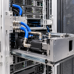
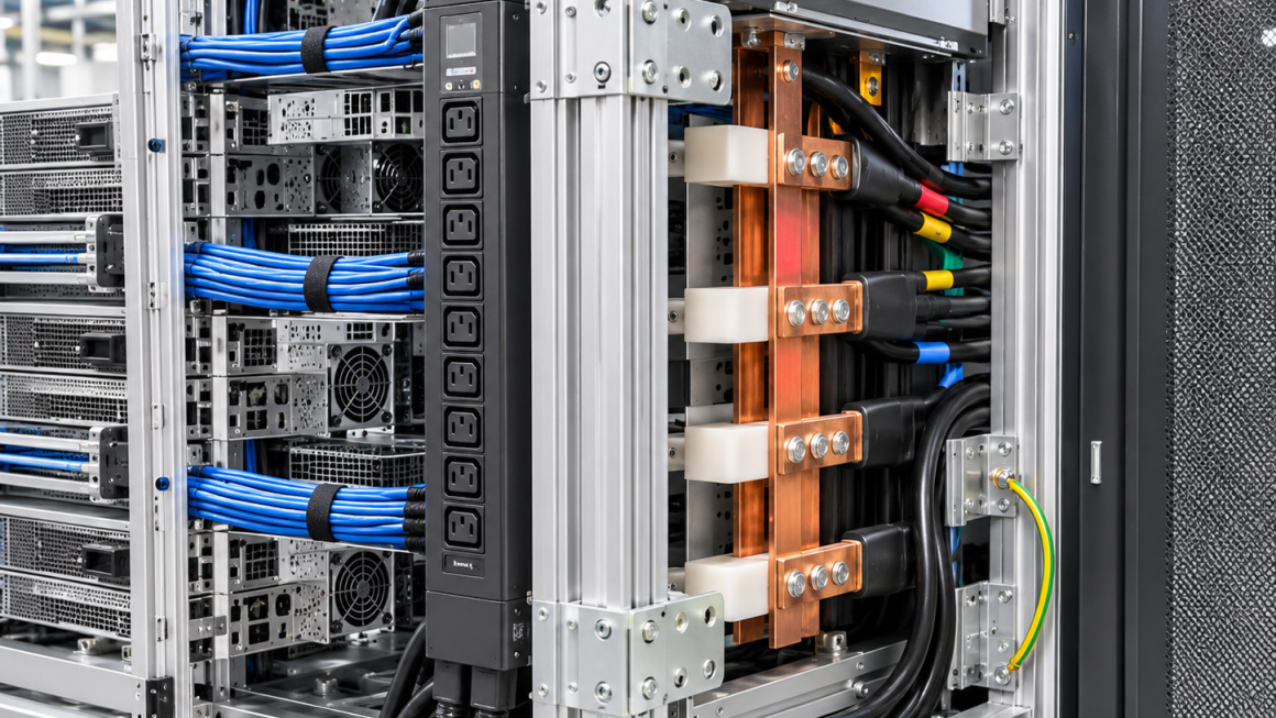
Modern AI racks may accommodate multiple power distribution units (PDUs), busbar assemblies, power shelves, power cables, connectors, and monitoring equipment. These components must be installed within a limited space while maintaining structural stability, electrical safety, thermal management, and serviceability.
The rack structure plays an important role in supporting this complex arrangement.
Aluminum is widely used in equipment frames, mounting rails, structural profiles, brackets, cable guides, and custom mechanical assemblies because of its relatively low weight, manufacturing flexibility, and corrosion resistance under suitable conditions.
However, designing an aluminum AI rack for high-density power distribution involves more than selecting an appropriate extrusion profile.
Engineers must coordinate the mechanical support system with electrical insulation requirements, cable routing, grounding architecture, airflow, and maintenance access.
One distinction is particularly important: aluminum rack structures provide mechanical support, but they should not automatically be treated as electrical busbars or protective grounding conductors. Electrical current paths and protective bonding arrangements must be independently designed and verified.
This article explores the main engineering considerations involved in designing aluminum rack structures for high-density AI power distribution.
2. Understanding the Mechanical Requirements of AI Rack Power Distribution
High-density power distribution systems introduce several mechanical requirements that traditional server racks may not fully address.
A rack may need to support:
- Rack-mounted PDUs
- Vertical or horizontal busbar assemblies
- Power shelves and power conversion modules
- High-current connectors
- Cable management brackets
- Power distribution enclosures
- Monitoring and control equipment
- Protective covers and access panels
Each component introduces its own mounting, loading, clearance, and maintenance requirements.
The aluminum structure must provide stable mounting interfaces while accommodating the dimensions and tolerances of the electrical equipment.
2.1 Equipment Mounting and Load Distribution
Power distribution equipment can create concentrated loads at specific mounting points.
For example, a vertical PDU or a power distribution enclosure may transfer its weight through a limited number of brackets or mounting rails.
The rack design should consider:
- Equipment weight and center of gravity
- Mounting-hole locations
- Fastener type and engagement length
- Local profile wall thickness
- Bracket stiffness
- Load transfer into the main frame
- Dynamic loads during installation and maintenance
Where heavy equipment is mounted on aluminum profiles, local reinforcement may be required.
Possible solutions include thicker-wall extrusions, reinforced brackets, cross-members, backing plates, or dedicated mounting interfaces.
The appropriate arrangement depends on the equipment load, profile geometry, connection design, and required structural performance.
2.2 Mounting Repeatability
AI infrastructure is often assembled in standardized configurations or deployed across multiple racks.
Mounting interfaces should therefore support consistent installation.
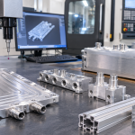
Custom aluminum extrusions and CNC-machined brackets can provide:
- Repeatable equipment positioning
- Defined mounting-hole patterns
- Consistent bracket alignment
- Modular equipment installation
- Easier replacement of individual assemblies
This is especially useful when different rack configurations share a common structural platform.
3. Designing AI Rack Busbar Support Structures
Busbar systems are commonly used in high-power electrical distribution because they can provide organized, compact current distribution.
However, busbar assemblies require dedicated electrical and mechanical engineering.
The aluminum rack structure should support the busbar system without compromising its insulation, spacing, or electrical protection requirements.
3.1 Mechanical Support for Busbar Assemblies
An AI rack busbar support structure may include:
- Vertical support rails
- Insulating support brackets
- Mechanical mounting plates
- Protective covers
- Alignment features
- Removable support members
- Cable and connector retention brackets
The support arrangement must account for the busbar assembly’s weight, installation loads, and relevant electromechanical forces.
For systems exposed to high fault currents, the busbar and its support system must be evaluated for the mechanical forces associated with the specified fault conditions.
The aluminum rack frame should not be assumed to provide sufficient support simply because it has adequate static load capacity.
3.2 Electrical Isolation Between Busbars and Aluminum Structures
Aluminum is electrically conductive.
Therefore, direct contact between an energized busbar and an aluminum structural member can create an electrical hazard if the contact is not part of an intentionally designed electrical arrangement.
Depending on the system architecture, isolation may require:
- Insulating support blocks
- Nonconductive mounting brackets
- Insulating barriers
- Protective covers
- Defined creepage and clearance distances
- Insulated fasteners or bushings where appropriate
The actual insulation arrangement must be determined by the electrical design, voltage level, pollution conditions, material properties, and applicable safety standards.
Simply adding a plastic spacer does not automatically establish adequate electrical insulation.
The complete assembly must be evaluated under its intended operating and environmental conditions.
3.3 Busbar Alignment and Tolerance Control
Misalignment between busbars, connectors, and power distribution equipment can create installation difficulties and mechanical stress.
The rack structure should provide sufficient dimensional control to maintain the intended connection geometry.
Important considerations include:
- Positioning tolerance of mounting rails
- Parallelism of support members
- Bracket flatness
- Connector engagement requirements
- Thermal expansion allowance
- Access for installation tools
CNC-machined aluminum brackets and precision extrusion profiles can help establish repeatable mechanical interfaces.
For complex rack configurations, a tolerance review should be conducted across the complete assembly rather than evaluating each individual component separately.
4. Electrical Clearance and Insulation Considerations
High-density power distribution requires careful control of electrical spacing.
The mechanical structure can directly affect the available space around energized components.
4.1 Clearance and Creepage Distance
Two important electrical insulation concepts are clearance and creepage distance.
Clearance refers to the shortest distance through air between conductive parts.
Creepage distance refers to the shortest distance along the surface of an insulating material between conductive parts.
Both are influenced by the electrical design and operating environment.
Relevant factors may include:
- Working voltage
- Transient overvoltage
- Insulation coordination
- Pollution degree
- Material properties
- Environmental conditions
- Applicable electrical safety standards
The required distances should be established by the responsible electrical engineer.
The aluminum rack structure must be designed so that mounting brackets, fasteners, cable guides, and removable panels do not unintentionally reduce the required electrical separation.
4.2 Insulating Components and Structural Interfaces
In some designs, insulating components are installed between the aluminum frame and electrical equipment.
These may include:
- Polymer mounting blocks
- Insulating washers
- Protective sleeves
- Insulating plates
- Cable support components
The selected material should be evaluated for mechanical strength, temperature resistance, aging, flammability requirements, and electrical insulation performance.
For applications near power conversion equipment, the material must also be suitable for the expected thermal and environmental conditions.
4.3 Preventing Accidental Contact
Structural edges, protruding fasteners, and loose metal parts can create risks around electrical assemblies.
Mechanical design should address:
- Exposed conductive edges
- Unintended contact with energized terminals
- Fastener protrusion
- Cable abrasion
- Loose metallic debris
- Access openings near electrical equipment
Protective covers and appropriately designed cable barriers can help reduce accidental contact and mechanical damage.
5. Power Cable Management in High-Density AI Racks
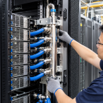
Power cable management is one of the most important integration challenges in high-density AI racks.
A large number of power cables may need to pass through limited spaces while maintaining acceptable bend radii, connector accessibility, airflow, and separation from other systems.
A well-designed aluminum rack structure should provide organized cable routing rather than simply creating additional attachment points.
5.1 Dedicated Cable Routing Paths
Cable routing should be planned during the initial rack design.
Possible structural solutions include:
- Vertical cable channels
- Horizontal cable trays
- Side-mounted cable guides
- Rear cable management brackets
- Removable routing covers
- Dedicated connector support brackets
The routing layout should accommodate the actual cable dimensions, connector geometry, and installation sequence.
Where power and signal cables require separation, the rack should provide suitable independent routing paths or barriers according to the electrical and system requirements.
5.2 Bend Radius and Cable Protection
Power cables should not be forced into excessively tight bends.
The minimum bend radius should follow the cable manufacturer’s specifications and the applicable installation requirements.
The rack structure should provide enough space for:
- Cable entry and exit
- Connector installation
- Bend-radius control
- Cable movement during servicing
- Protection against sharp edges
- Retention without excessive compression
Rounded edges, protective grommets, cable clamps, and polymer guides can help reduce abrasion and localized mechanical stress.
5.3 Cable Weight and Mechanical Support
In large AI racks, multiple power cables can create considerable cumulative weight.
The cable management structure should prevent this load from being transferred unintentionally to electrical connectors.
Cable support brackets and retention systems should be designed to carry the expected cable load while maintaining appropriate routing geometry.
The connection point should not become the primary mechanical support for a long or heavy cable unless the connector system is specifically designed for that purpose.
5.4 Airflow and Cable Congestion
Poor cable routing can obstruct airflow and make equipment maintenance difficult.
Although power cable routing is primarily an electrical and mechanical design task, it can influence thermal performance.
The rack layout should consider:
- Airflow paths around power shelves
- Space behind electrical equipment
- Cable density near ventilation openings
- Heat generated by power conversion equipment
- Access to fans and replaceable modules
Cable routing should be coordinated with the rack’s overall thermal management strategy.
6. Grounding and Bonding: A Separate Electrical Design Requirement
Grounding and bonding must be addressed independently from the mechanical design of the aluminum rack.
Because aluminum is conductive, structural members may be included in an engineered protective bonding arrangement.
However, this does not mean that every aluminum profile, joint, or bolted connection automatically provides a reliable protective earth path.
6.1 Protective Bonding of Aluminum Structures
A protective bonding arrangement may include designated bonding points, conductors, terminals, and connections between conductive exposed parts.
The design should consider:
- Electrical continuity across structural joints
- Contact resistance
- Oxide layers on aluminum surfaces
- Coatings and anodized finishes
- Fastener and washer configurations
- Corrosion at dissimilar-metal interfaces
- Long-term mechanical stability
Aluminum naturally forms an oxide layer, and surface treatments such as anodizing can further influence electrical contact behavior.
Consequently, a mechanical bolted joint should not be assumed to provide a reliable electrical bonding connection without appropriate design and verification.
6.2 Dedicated Grounding Interfaces
Where required, dedicated grounding points can be incorporated into the rack design.
Examples include:
- Machined bonding pads
- Designated grounding studs
- Conductive bonding hardware
- Accessible grounding terminals
- Clearly defined bonding locations
These interfaces should be coordinated with the electrical grounding architecture and verified using the specified continuity or bonding tests.
6.3 Distinguishing Structural Aluminum from Electrical Conductors
An aluminum frame is not automatically a substitute for a dedicated busbar or protective grounding conductor.
The design should clearly distinguish:
- Mechanical support provided by aluminum profiles and brackets
- Electrical current distribution provided by appropriately rated busbars and conductors
- Protective bonding provided by an engineered grounding system
Maintaining this distinction is essential for safe and predictable rack-level power integration.
7. Thermal Expansion and Structural Stability
Aluminum has a relatively high coefficient of thermal expansion compared with many other structural and electrical materials.
In high-density AI racks, temperature differences can develop between:
- Aluminum frame members
- Copper or other metal busbars
- Power conversion equipment
- Insulating support materials
- Cable assemblies
These differences may affect mounting alignment and connection stress.
7.1 Differential Expansion
Where an aluminum support structure carries a busbar assembly made from another material, the design should account for differential thermal expansion.
Depending on the assembly, possible design approaches include:
- Controlled sliding interfaces
- Expansion allowances
- Flexible mounting arrangements
- Defined fastening locations
- Suitable insulating support materials
The correct approach depends on the electrical assembly and its operating temperature range.
7.2 Maintaining Connection Geometry
Thermal expansion should not cause excessive mechanical loading on busbar connections, connectors, or power distribution equipment.
The rack should provide sufficient structural stiffness while allowing the movement required by the system design.
Thermal and mechanical validation may be appropriate for high-power configurations or assemblies with significant temperature variation.
8. Designing for Installation and Maintenance
High-density AI racks are complex systems. Maintenance accessibility should therefore be considered during the structural design stage.
Power distribution components may require inspection, replacement, or reconfiguration during the rack’s service life.
8.1 Removable Mounting Brackets
Modular brackets and mounting plates can simplify installation and replacement.
For example, a PDU support bracket may be designed as a removable assembly without requiring the complete rack frame to be dismantled.
This can reduce maintenance complexity and improve component accessibility.
8.2 Access to Electrical Connections
The mechanical structure should provide sufficient space for authorized personnel to access designated connection points according to the equipment manufacturer’s service procedures.
Consider:
- Fastener access
- Connector removal clearance
- Cable disconnection space
- Protective cover removal
- Tool access
- Inspection visibility
Electrical safety procedures and equipment isolation requirements must always be followed during maintenance.
8.3 Cable Replacement and Reconfiguration
AI rack configurations may change as servers, power modules, or distribution equipment are upgraded.
Cable management structures should allow appropriate cable replacement without requiring unnecessary dismantling of unrelated equipment.
Removable guides, modular trays, and accessible routing channels can support this requirement.
8.4 Clear Identification and Documentation
Mechanical interfaces should support clear identification of equipment and cable routes.
Labels, mounting references, and assembly drawings can help maintenance teams identify individual components and reduce installation errors.
The identification system should be coordinated with the electrical documentation.
9. Aluminum Manufacturing Solutions for AI Rack Power Distribution Structures
The choice of aluminum manufacturing process depends on the required geometry, mechanical performance, production volume, and integration requirements.
9.1 Custom Aluminum Extrusions
Custom extrusions can provide integrated mounting features and modular structural interfaces.
Potential applications include:
- Vertical rack rails
- Horizontal support beams
- PDU mounting profiles
- Cable management channels
- Busbar support frame members
- Equipment mounting structures
Extrusion design can integrate slots, grooves, and mounting features to reduce the number of separate components.
9.2 CNC-Machined Aluminum Brackets
CNC machining is useful for producing precision interfaces where alignment and dimensional control are important.
Typical applications include:
- Busbar support brackets
- PDU mounting plates
- Reinforced structural connectors
- Grounding interface components
- Custom equipment adapters
The machining process can accommodate specific mounting-hole patterns and interface dimensions.
9.3 Sheet Metal and Aluminum Plate Components
Aluminum sheet and plate fabrication can support the production of:
- Protective covers
- Cable routing panels
- Equipment mounting plates
- Structural reinforcement panels
- Removable access panels
Bending, CNC machining, fastening, and assembly processes can be combined to produce integrated rack subassemblies.
9.4 Surface Treatment
Surface treatments may include anodizing, conversion coatings, and other application-specific finishes.
The treatment should be selected according to corrosion resistance, appearance, wear requirements, and electrical interface considerations.
Where electrical bonding is required, the designated contact areas must be addressed in the surface-treatment and assembly specifications.
Anodizing should not be assumed to provide electrical conductivity at a contact interface.
10. Quality Control and Validation
A reliable aluminum AI rack power distribution structure requires both mechanical and electrical integration checks.
A practical quality-control plan may include the following areas.
| Validation area | Key inspection considerations |
|---|---|
| Structural integrity | Load capacity, deflection, joint stability |
| Mounting accuracy | Hole positions, alignment, interface dimensions |
| Busbar support | Mechanical stability and mounting consistency |
| Electrical clearance | Required spacing and insulation arrangements |
| Cable management | Routing, bend radius, retention, edge protection |
| Grounding interfaces | Bonding-point design and electrical continuity verification |
| Thermal behavior | Expansion allowance and interface stability |
| Surface treatment | Coating condition and functional contact areas |
| Serviceability | Access, removability, and maintenance clearance |
Electrical validation should be performed by appropriately qualified personnel using the applicable equipment specifications and standards.
Mechanical inspection alone cannot establish electrical safety.
For production programs, drawings, inspection reports, material records, and assembly documentation should be maintained with appropriate revision control.
11.
Designing aluminum AI racks for high-density power distribution requires close coordination between mechanical structure, electrical equipment, and system integration.
The aluminum rack structure must provide reliable mounting support for PDUs, busbar assemblies, power shelves, and cable management hardware while maintaining dimensional accuracy, structural stability, and service accessibility.
At the same time, electrical clearance, insulation, grounding, and protective bonding must be independently engineered and validated.
Aluminum profiles and CNC-machined brackets can provide flexible mechanical solutions, but they should not be confused with dedicated electrical conductors or assumed to provide protective grounding without verification.
At Aluminum4AI, we support custom aluminum extrusion, CNC machining, structural brackets, mounting rails, and integrated mechanical components for AI infrastructure applications.
By coordinating structural design with electrical equipment interfaces and maintenance requirements, manufacturers can develop scalable aluminum rack platforms for increasingly demanding AI power distribution environments.