As AI servers become heavier and more densely packed, the mechanical performance of the supporting aluminum infrastructure becomes increasingly important.
Modern AI systems may contain high-density GPU modules, liquid-cooling equipment, power distribution components, cables, manifolds, and other hardware within the same rack or chassis.
The aluminum structures supporting these systems must therefore do more than simply hold components in place.
They need to maintain:
- Structural strength
- Dimensional stability
- Mounting accuracy
- Low deformation
- Vibration resistance
- Long-term reliability
- Serviceability
This makes aluminum AI server structural testing an important part of engineering validation.
A component can meet its dimensional drawing and still fail under real operating loads.
Similarly, an aluminum rack can support the required static weight but experience excessive deformation or vibration during operation.
For this reason, structural validation should examine how the finished component or assembly behaves under realistic mechanical conditions.
A practical testing sequence is:
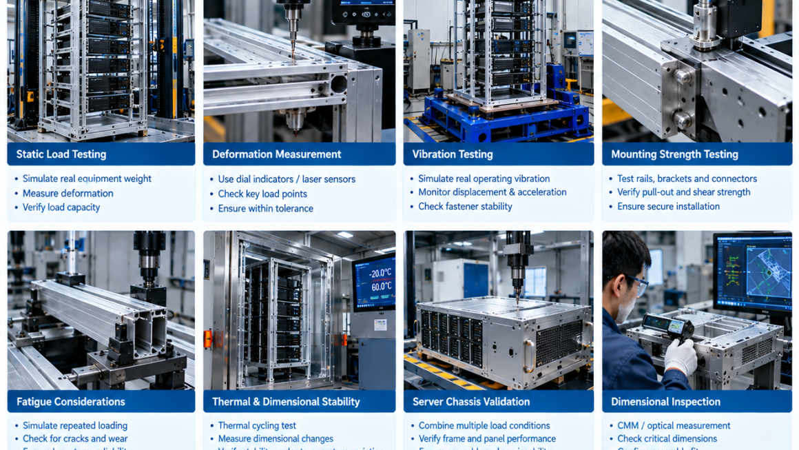
Design → Simulation → Prototype → Static Load Testing → Deformation Measurement → Vibration Testing → Mounting Validation → Fatigue Consideration → Production Validation
Why Mechanical Testing Matters for AI Server Structures
AI infrastructure places increasingly concentrated loads on physical structures.
A conventional server rack may distribute equipment weight relatively evenly.
An AI rack may contain concentrated loads around:
- GPU servers
- Power supplies
- Cooling manifolds
- Cold plates
- Pumps
- Busbars
- Battery or backup-power components
The resulting load path can be significantly different.
An aluminum frame therefore needs to be evaluated as a structural system rather than simply as a collection of aluminum profiles.
Mechanical testing helps answer practical questions:
- Can the structure support the required load?
- How much does it deform?
- Does the deformation remain within acceptable limits?
- Are mounting interfaces stable?
- Can the structure withstand vibration?
- Will repeated loading affect the joints?
- Does the structure maintain dimensional accuracy over time?
Static Load Testing
Static load testing is one of the most fundamental forms of AI rack mechanical testing.
The objective is to apply a defined load and measure how the structure responds.
Depending on the application, the test may simulate:
- GPU server weight
- Rack-mounted equipment
- Cooling systems
- Power distribution hardware
- Cable loads
- Accessories
- Combined system loads
The load should be applied at locations representative of the actual equipment.
Simply placing a large weight at the center of a frame may not reproduce the real load path.
Understanding the Load Path
Before testing, engineers should understand how forces move through the structure.
For a typical AI server rack, the load path may be:
Server → Mounting Rails → Vertical Profiles → Horizontal Frame → Base → Floor
If liquid cooling equipment is attached to the structure, additional forces may enter through:
Manifold → Mounting Bracket → Rack Frame
Hoses can also introduce localized forces through:
- Bending
- Tension
- Vibration
- Thermal expansion
Understanding these load paths helps determine where test loads should be applied.
Static Load Test Setup
A representative static load test may include:
- Installing the aluminum structure on its intended support points.
- Installing representative mounting hardware.
- Applying the specified load.
- Measuring deformation.
- Holding the load for a defined period.
- Removing the load.
- Measuring residual deformation.
Measurements may be taken at:
- Rack corners
- Center spans
- Mounting rails
- Critical brackets
- Chassis interfaces
The exact test method should be based on the structural requirements of the application.
Load Capacity vs. Allowable Deformation
Structural strength is not the only consideration.
A structure may technically support a load without breaking but still deform too much for the application.
Excessive deformation can affect:
- Server alignment
- Rail installation
- Door operation
- Cooling connections
- Cable routing
- Connector alignment
- Sealing interfaces
Therefore, structural validation should consider both:
Strength
and
Stiffness
Strength determines whether the structure can withstand the load.
Stiffness determines how much it moves under that load.
For AI server infrastructure, both can be important.
Measuring Deformation
Deformation can be measured using:
- Dial indicators
- Laser displacement sensors
- Digital displacement sensors
- CMM systems
- Optical measurement
- Strain gauges where appropriate
The measurement points should be defined before testing.
For example, a rack frame may be evaluated for:
- Vertical deflection
- Horizontal displacement
- Twist
- Local bracket deformation
The results can then be compared with the design limits.
Permanent Deformation
After a static load is removed, the structure should be checked for residual deformation where applicable.
This helps distinguish between:
Elastic deformation
and
Permanent deformation
Elastic deformation means the structure returns approximately to its original position after the load is removed.
Permanent deformation indicates that some part of the structure or connection has undergone irreversible change.
For critical server structures, residual deformation should be evaluated according to the defined acceptance criteria.
Localized Load Testing
AI infrastructure can contain highly concentrated loads.
For example, a heavy GPU server may apply significant load at specific mounting points rather than evenly across an entire rack.
Localized testing can therefore be useful.
Test loads may be applied at:
- Rail mounting points
- Brackets
- Equipment support points
- Cooling-module mounts
- Power-system mounts
This can reveal local weaknesses that may not appear during uniform loading.
Aluminum Frame Testing
For an aluminum server frame, testing should consider the complete structure.
Important elements may include:
- Extruded profiles
- CNC-machined brackets
- Fasteners
- Corner connections
- Mounting rails
- Reinforcement members
- Base structures
The aluminum profile itself may have sufficient strength, but the complete assembly can still be limited by the connection.
This is why aluminum frame testing should include both structural members and their joints.
Connection and Mounting Strength
Connections often become critical points in lightweight aluminum structures.
Common connection methods include:
- Bolted joints
- T-slot connections
- Machined brackets
- Riveted joints
- Threaded inserts
- Custom connectors
Testing may evaluate:
- Pull-out strength
- Shear strength
- Joint deformation
- Fastener stability
- Repeated loading
A structure is only as strong as the load path through its connections.
Mounting Rail Validation
Server rails provide a critical interface between the equipment and the rack.
Testing should consider:
- Rail load capacity
- Rail deflection
- Mounting-hole accuracy
- Fastener strength
- Repeated insertion and removal
- Alignment
This is especially important for dense AI servers because individual equipment modules can be significantly heavier than conventional computing equipment.
Bracket Testing
Brackets connecting cooling equipment, manifolds, power components, or structural members should also be validated.
A bracket may experience multiple loads simultaneously.
For example:
Vertical load + lateral load + vibration + thermal expansion
Testing can therefore go beyond a simple downward load.
Where appropriate, combined loading should be considered.
Vibration Testing
AI infrastructure operates in environments where vibration may originate from:
- Cooling fans
- Pumps
- Power equipment
- Nearby machinery
- Building systems
- Transportation during shipment
Vibration can cause:
- Fastener loosening
- Joint movement
- Fatigue
- Noise
- Connector displacement
- Structural resonance
This makes vibration testing an important consideration for certain AI server structures.
Vibration Testing of Aluminum Frames
A vibration test may expose the structure to controlled vibration frequencies and amplitudes.
Engineers may monitor:
- Structural displacement
- Acceleration
- Resonance
- Fastener movement
- Joint stability
- Component response
The objective is not necessarily to eliminate all vibration.
Instead, the goal is to ensure that the structure remains within acceptable mechanical limits under expected operating conditions.
Natural Frequency and Resonance
Every structural system has natural frequencies.
If an excitation frequency approaches a structural natural frequency, vibration response can increase significantly.
For an AI server rack, potential excitation sources include:
- Fan rotation
- Pump operation
- Rotating machinery
- Building vibration
Structural simulation can help identify potential resonance conditions.
Physical vibration testing can then validate the actual structure.
A practical approach is:
FEA → Prototype → Modal Testing → Vibration Validation
Mounting Strength Under Dynamic Loads
A mounting point that performs well under static loading may behave differently under vibration.
Repeated dynamic forces can cause:
- Fastener loosening
- Joint slip
- Local deformation
- Fatigue cracks
- Bracket movement
Therefore, critical mounting interfaces should be considered under both static and dynamic conditions.
Fatigue Considerations
AI infrastructure may remain in operation for years.
Even when the operating load is below the static strength limit, repeated loading can gradually affect a component.
Potential cyclic loads include:
- Equipment vibration
- Pump vibration
- Fan vibration
- Thermal expansion and contraction
- Repeated maintenance
- Equipment installation and removal
Fatigue analysis can therefore become relevant for components exposed to repeated mechanical loading.
Aluminum Fatigue Behavior
Aluminum alloys behave differently from some steels under cyclic loading.
For many aluminum alloys, fatigue performance does not necessarily show the same type of clear endurance limit commonly used for some steels.
Therefore, fatigue design should consider:
- Stress amplitude
- Number of cycles
- Mean stress
- Stress concentration
- Surface condition
- Joint design
- Material condition
For critical structures, fatigue calculations and testing should be based on the specific alloy, geometry, loading conditions, and applicable design requirements.
Stress Concentration
Small geometric features can create local stress concentrations.
Examples include:
- Sharp internal corners
- Holes
- Threads
- Slots
- Machined pockets
- Abrupt section changes
These features can become important during fatigue or high-load testing.
Good structural design often uses:
- Appropriate radii
- Smooth transitions
- Adequate material around holes
- Proper reinforcement
The objective is to avoid unnecessary localized stress.
Thermal Expansion and Mechanical Stability
AI infrastructure can experience significant temperature changes.
Aluminum expands and contracts with temperature.
This can affect:
- Rack dimensions
- Cold plate interfaces
- Mounting brackets
- Manifolds
- Seals
- Fasteners
For example, a cooling manifold attached rigidly to a large aluminum frame may experience additional mechanical stress as temperatures change.
Mechanical validation may therefore need to consider thermal expansion together with structural loading.
Dimensional Stability
A critical objective of server chassis validation is maintaining dimensional stability.
Important dimensions may include:
- Server mounting points
- Rail spacing
- Chassis width
- Chassis height
- Connector locations
- Cooling interfaces
- Door or panel alignment
A structure can remain mechanically intact while gradually becoming difficult to assemble if dimensional stability is not controlled.
Thermal Cycling and Dimensional Stability
Repeated temperature changes can produce repeated expansion and contraction.
A useful validation program for selected components may combine:
Thermal Cycling → Mechanical Inspection → Functional Assembly Check
Measurements can identify:
- Permanent deformation
- Alignment changes
- Joint movement
- Interface displacement
This is especially relevant for structures combining aluminum with steel, copper, polymers, or other materials with different thermal expansion characteristics.
Server Chassis Validation
An AI server chassis often needs to perform several functions simultaneously.
It may need to:
- Support GPU modules
- Hold cooling components
- Provide cable management
- Protect electronics
- Maintain dimensional alignment
- Provide service access
Mechanical testing should therefore evaluate the chassis as an integrated assembly.
Potential tests include:
- Static load
- Localized load
- Mounting strength
- Vibration
- Shock where applicable
- Thermal cycling
- Dimensional inspection
Chassis Door and Panel Testing
Panels and doors may appear secondary, but they can influence structural and serviceability performance.
Testing may evaluate:
- Hinge strength
- Latch strength
- Panel deformation
- Repeated opening and closing
- Alignment
- Fastener stability
For high-serviceability AI infrastructure, repeated access can create mechanical wear over the system’s lifecycle.
Repeated Assembly and Service Testing
AI equipment may be removed and replaced many times during its operational life.
This means certain interfaces can experience repeated mechanical cycles.
Potential test conditions include:
- Server insertion
- Server removal
- Rail engagement
- Connector mounting
- Panel removal
- Fastener installation
Repeated assembly testing can reveal:
- Thread wear
- Insert failure
- Bracket deformation
- Alignment problems
- Fastener damage
This can be particularly valuable for modular AI infrastructure.
Shock and Transportation Considerations
A component may be mechanically sound during normal operation but experience higher loads during transportation.
Depending on the product, shipping validation may consider:
- Shock
- Vibration
- Packaging support
- Mounting security
This is especially relevant for:
- Pre-assembled server chassis
- Modular cooling units
- Edge AI enclosures
- Integrated aluminum systems
Transportation testing should be considered separately from operating vibration because the load conditions can be very different.
Finite Element Analysis Before Physical Testing
FEA can help identify potential structural problems before building multiple prototypes.
Engineers can analyze:
- Stress
- Deflection
- Load distribution
- Connection forces
- Natural frequencies
- Thermal deformation
For AI server structures, FEA can be particularly useful for evaluating concentrated GPU loads.
However, simulation should be supported by physical testing.
The actual manufactured component contains:
- Material variation
- Fastener tolerances
- Extrusion variation
- Machining variation
- Joint friction
- Assembly variation
Physical testing provides evidence that the manufactured structure behaves as expected.
Correlating FEA With Physical Testing
A useful validation process is:
FEA Prediction
↓
Prototype Manufacturing
↓
Physical Mechanical Test
↓
Compare Results
↓
Update Model
↓
Design Optimization
This approach can improve the accuracy of future structural designs.
It also helps engineers understand where simulation assumptions may differ from real-world behavior.
Static Load Test Example
Consider an aluminum AI server frame designed to support several heavy computing modules.
A simplified validation program might include:
Test 1 — Normal Operating Load
Apply the expected maximum equipment load.
Measure:
- Vertical deflection
- Horizontal movement
- Local deformation
Test 2 — Localized Load
Apply concentrated loads at critical mounting points.
Measure:
- Local deformation
- Joint response
- Mounting stability
Test 3 — Load Removal
Remove the load and measure residual deformation.
Test 4 — Extended Hold
Maintain the defined load for a specified period and monitor structural stability.
The exact loads and acceptance criteria should be established from the actual engineering design.
Mechanical Testing of Liquid-Cooling Structures
Liquid cooling adds mechanical loads to the infrastructure.
Cooling components may experience:
- Internal pressure
- Hose forces
- Connector forces
- Pump vibration
- Thermal expansion
- Maintenance loads
Therefore, a liquid-cooling structural support should not be evaluated only as a static bracket.
Testing may combine:
Mechanical load + pressure + vibration + thermal cycling
where required by the application.
Hose and Connector Forces
Quick-disconnect couplings and hoses can transmit mechanical loads into an aluminum structure.
Potential forces come from:
- Hose bending
- Hose tension
- Connector insertion
- Connector removal
- Thermal movement
A bracket should therefore provide sufficient support without making the cooling interface excessively rigid.
This is another example of why mechanical and thermal design should be considered together.
Quality Control After Mechanical Testing
Mechanical validation should connect back to production quality control.
After testing, components may be inspected for:
- Cracks
- Permanent deformation
- Fastener movement
- Surface damage
- Dimensional changes
- Joint displacement
If a structural test causes unexpected deformation, the result should trigger an engineering investigation rather than simply being recorded as a test failure.
Possible causes include:
- Incorrect material
- Insufficient wall thickness
- Poor joint design
- Unexpected load path
- Manufacturing variation
Production Validation
A successful prototype test does not automatically guarantee production consistency.
During pilot production, representative production parts can be tested to confirm:
- Material consistency
- Dimensional stability
- Structural performance
- Joint performance
- Manufacturing repeatability
This creates a useful chain:
Prototype Validation → Pilot Validation → Production Quality Control
Mechanical Test Acceptance Criteria
Before testing begins, acceptance criteria should be defined.
Depending on the component, these may include:
- Maximum allowable deformation
- No permanent deformation
- No cracking
- No joint separation
- No fastener failure
- Maximum vibration response
- Dimensional tolerance after testing
Testing without predefined acceptance criteria can make results difficult to interpret.
Common Mechanical Testing Mistakes
1. Testing Only the Aluminum Profile
The complete assembly may fail at the connection rather than in the profile.
2. Testing Only Uniform Loads
AI hardware often creates concentrated loads.
3. Ignoring Deformation
Structural failure is not limited to breakage.
4. Ignoring Fasteners
Connections can determine overall structural performance.
5. Testing Static Load but Not Vibration
Dynamic loading may introduce different failure mechanisms.
6. Ignoring Thermal Expansion
Temperature changes can alter alignment and joint forces.
7. Testing Only One Prototype
Production variation should also be considered.
8. Using Simulation Without Physical Validation
FEA is a design tool, not a substitute for all physical testing.
A Practical Mechanical Validation Workflow
A structured approach can reduce development risk.
Step 1 — Define Structural Requirements
Identify:
- Maximum load
- Load locations
- Allowable deformation
- Operating environment
- Expected service life
Step 2 — Develop the Structural Model
Use CAD and FEA to evaluate:
- Stress
- Deflection
- Load paths
- Natural frequencies
Step 3 — Manufacture the Prototype
Use production-relevant aluminum material and manufacturing methods where practical.
Step 4 — Conduct Static Load Testing
Measure deformation and structural response.
Step 5 — Validate Mounting Interfaces
Test rails, brackets, fasteners, and connections.
Step 6 — Conduct Vibration Testing
Evaluate dynamic response where required.
Step 7 — Consider Fatigue
Identify components exposed to repeated loading.
Step 8 — Evaluate Thermal and Dimensional Stability
Where temperature changes are significant, perform thermal-mechanical validation.
Step 9 — Validate Pilot Production
Confirm that production-intent components reproduce the required performance.
Step 10 — Establish Production Controls
Monitor critical dimensions, materials, joints, and assembly processes.
Mechanical Test Matrix for AI Aluminum Structures
| Test | Primary Purpose | Typical Components |
|---|---|---|
| Static load | Verify load capacity and deformation | Rack, frame, chassis |
| Localized load | Verify concentrated-load resistance | Rails, brackets |
| Mounting strength | Verify interfaces and connections | Rails, brackets, inserts |
| Vibration | Evaluate dynamic stability | Rack, chassis, cooling structures |
| Fatigue | Evaluate repeated loading | Frames, brackets, joints |
| Thermal cycling | Evaluate dimensional stability | Chassis, cooling structures |
| Dimensional inspection | Verify geometry | All precision components |
| Shock/transport test | Evaluate shipping robustness | Modular systems |
| Post-test inspection | Identify permanent changes | Critical structures |
The actual test matrix should be based on the component’s risk, operating environment, and customer requirements.
Designing Aluminum Structures for Testability
Testing should be considered during design.
A component that is easy to measure is easier to validate.
Engineers can provide:
- Accessible measurement points
- Defined loading locations
- Reference datums
- Replaceable test fixtures
- Clear inspection surfaces
This can reduce test complexity and improve repeatability.
From Structural Design to Production
Mechanical testing should not be an isolated engineering activity.
The results should feed back into:
- Aluminum alloy selection
- Profile geometry
- Wall thickness
- Reinforcement
- Bracket design
- Fastener selection
- Extrusion design
- CNC machining
- Quality control
For example, if testing reveals excessive deflection in an aluminum profile, possible solutions may include:
- Increasing section stiffness
- Changing profile geometry
- Adding reinforcement
- Reducing unsupported span
- Improving connection design
The best solution is not necessarily to use more material.
It may be to improve the structural architecture.
As AI server systems become heavier, denser, and more complex, the mechanical performance of their supporting aluminum infrastructure becomes increasingly important.
Aluminum AI server structural testing should go beyond simply checking whether a component breaks.
A comprehensive validation strategy may include:
- Static load testing
- Deformation measurement
- Localized load testing
- Mounting strength
- Vibration testing
- Fatigue considerations
- Thermal-mechanical testing
- Dimensional stability
- Post-test inspection
- Production validation
For AI rack mechanical testing, the load path and actual operating conditions should be reproduced as realistically as practical.
For aluminum frame testing, both structural profiles and connection systems need to be considered.
For server chassis validation, dimensional stability, mounting accuracy, serviceability, and long-term mechanical behavior can all be important.
The strongest approach is to combine simulation and physical validation:
FEA → Prototype → Static Load Test → Vibration / Fatigue Evaluation → Thermal-Mechanical Validation → Pilot Production → Production Quality Control
Ultimately, the purpose of mechanical testing is not simply to generate a test report.
It is to demonstrate that the aluminum structure can support the equipment, maintain its geometry, survive expected mechanical conditions, and continue to perform reliably throughout its intended service life.
A strong aluminum structure is not defined only by its material strength.
It is defined by how reliably the complete structure performs under real operating loads.