Selecting aluminum components for an AI data center project involves much more than choosing an alloy or requesting a quotation.
AI infrastructure combines high-density computing hardware, demanding structural requirements, advanced thermal management, complex cable routing, and increasingly sophisticated liquid cooling systems. Each aluminum component must perform within a larger mechanical, thermal, and manufacturing system.
A structural frame may need to support concentrated GPU and server loads. A heat sink must transfer heat effectively while meeting airflow and dimensional constraints. A cooling manifold support must maintain alignment and withstand mechanical loads without obstructing hoses or service access.
These applications may all use aluminum, but they require different engineering priorities.
Understanding how to select aluminum components for AI data centers helps project teams avoid mismatched materials, unnecessary machining costs, difficult assembly, and performance problems during validation or production.
A reliable selection process begins with the application, not the material catalog.
1. Define the Component’s Function Before Selecting the Material
The first step is to identify what the aluminum component must accomplish.
A component’s primary function determines the properties that matter most.
Common applications include:
- AI server chassis and rack structures
- GPU support frames and mounting rails
- Aluminum heat sinks and heat spreaders
- Cold plate structures and cooling interfaces
- Cable trays and routing channels
- Equipment enclosures and access panels
- Liquid cooling manifold brackets
- Power distribution equipment housings
- Edge AI and outdoor equipment enclosures
These applications have different requirements.
For example, a structural beam is primarily evaluated by load capacity, stiffness, connection strength, and dimensional stability. A heat sink is evaluated by its thermal performance, fin geometry, airflow resistance, and manufacturing feasibility.
A manifold bracket may require a balance of stiffness, corrosion compatibility, machining precision, and service access.
Before requesting a quotation, define:
- The component’s primary function.
- Its operating environment.
- The mechanical and thermal loads it must withstand.
- The interfaces it must connect to.
- Its expected production quantity.
- The tests required for acceptance.
This information gives an aluminum infrastructure supplier a meaningful engineering basis for recommending a solution.
2. Select the Aluminum Alloy Based on Actual Requirements
Alloy selection is one of the most important decisions in aluminum component design.
However, no single aluminum alloy is ideal for every AI infrastructure application.
Two commonly considered extrusion and machining alloys are 6061 and 6063.
6061 Aluminum
6061 is widely used for machined structural components, mounting brackets, equipment supports, and parts requiring a useful combination of strength and machinability.
Potential applications include:
- CNC-machined structural brackets
- Load-bearing mounting components
- Precision equipment interfaces
- Custom structural blocks
- Reinforcement plates and support members
Its suitability depends on the specified temper, component geometry, loading conditions, and manufacturing route.
6063 Aluminum
6063 is widely used for extruded profiles, especially when profile geometry, surface appearance, and extrusion characteristics are important.
Potential applications include:
- Modular aluminum rack frames
- Structural extrusion profiles
- Cable management channels
- Equipment enclosure frames
- Heat sink profiles
- Custom mounting channels
Its suitability for a particular structural application must still be verified against the required strength, stiffness, connection design, and load cases.
6061 vs. 6063: A Practical Comparison
| Selection factor | 6061 | 6063 |
|---|---|---|
| Common application focus | Machined and structural components | Extruded profiles and complex sections |
| Machining | Commonly used for CNC machining | Can be machined where the application permits |
| Extrusion geometry | Suitable for many profiles | Often attractive for detailed extrusion geometries |
| Surface appearance | Depends on finish and process | Often selected for decorative or visible extrusions |
| Structural performance | Depends on temper and geometry | Depends on temper and geometry |
| Final selection | Based on loads, interfaces, and process | Based on profile design, loads, and process |
Important: Alloy designation alone does not establish component performance. Temper, material certification, section geometry, manufacturing history, and actual design loads must also be considered.
For critical components, specify the required alloy and temper rather than accepting an unspecified “aluminum profile.”
3. Evaluate Geometry and Structural Loads Together
A suitable alloy cannot compensate for poor structural geometry.
In AI racks and server chassis, loads may be concentrated around GPU assemblies, server rails, mounting points, and cooling equipment. These loads can create local deformation even when the overall structure appears sufficiently strong.
Important design factors include:
- Component length and unsupported span
- Cross-sectional area
- Wall thickness
- Section depth
- Reinforcing ribs
- Mounting hole locations
- Fastener spacing
- Connection stiffness
- Load distribution
- Torsional resistance
For extruded profiles, the cross-sectional shape can significantly influence stiffness and material efficiency.
For CNC-machined components, engineers must consider both the external geometry and the amount of material removed during machining.
For example, a thin-walled bracket may reduce weight but become sensitive to local bending around fastener holes. A deeper extrusion may provide better bending stiffness without requiring a solid, heavy section.
The appropriate solution depends on the actual load path.
Questions to ask before selecting a structural component
- What is the maximum supported load?
- Is the load distributed or concentrated?
- What deflection is acceptable?
- Will the component experience vibration?
- Are there repeated assembly or service loads?
- Does the component need to maintain alignment with cooling interfaces?
- Could future hardware upgrades increase the load?
Finite element analysis (FEA) can help evaluate stress and deformation, but critical assemblies should also be validated through physical testing.
4. Match the Component to Its Thermal Requirements
Thermal requirements vary substantially across AI infrastructure.
A heat sink, a cold plate support, and a general-purpose rack frame should not be selected using the same thermal criteria.
For thermal components, relevant factors may include:
- Thermal conductivity
- Heat spreading requirements
- Contact area
- Base thickness
- Fin geometry
- Airflow resistance
- Coolant channel geometry
- Interface flatness
- Thermal interface material
- Operating temperature range
Aluminum is useful for many thermal applications because it combines relatively high thermal conductivity with low density and flexible manufacturing options.
However, choosing an alloy with favorable thermal conductivity does not guarantee good cooling performance.
The complete thermal path matters.
For a typical heat sink, the path may be:
Heat source → thermal interface → aluminum base → fins → moving air
For a liquid-cooled component, the path may instead involve:
Heat source → thermal interface → cold plate → coolant → heat rejection system
Every interface can contribute thermal resistance.
When evaluating a thermal component, define measurable acceptance criteria such as:
- Maximum component temperature
- Thermal resistance under specified conditions
- Temperature uniformity
- Pressure drop for fluid-cooled components
- Coolant flow rate
- Operating pressure
- Thermal cycling performance
The required test conditions should be agreed upon before production rather than determined after samples have been delivered.
5. Choose the Right Manufacturing Process
Manufacturing method affects geometry, tolerances, tooling costs, lead time, and production consistency.
For AI infrastructure components, the main options often include aluminum extrusion, CNC machining, sheet metal fabrication, and combinations of these processes.
Aluminum Extrusion
Extrusion is useful for components with a consistent cross-section along their length.
Typical applications include:
- Rack profiles
- Modular structural beams
- Mounting channels
- Cable management profiles
- Heat sink profiles
- Equipment enclosure frames
It can be particularly attractive when a project requires repeatable geometry across multiple component lengths.
However, extrusion has geometric constraints. Profile complexity, wall thickness, dimensional tolerances, alloy selection, and tooling requirements must be evaluated together.
CNC Machining
CNC machining is useful when a component requires precise interfaces or features that cannot be produced economically through extrusion alone.
Applications include:
- Mounting holes and threaded features
- Precision mating surfaces
- Cooling component interfaces
- Custom brackets
- Manifold blocks
- Complex equipment housings
Machining can improve dimensional control, but excessive machining may increase cost and material waste.
Hybrid Manufacturing
For many AI infrastructure projects, combining extrusion and CNC machining provides an effective balance.
A common workflow is:
Extrusion → Cutting → CNC machining → Surface treatment → Inspection → Assembly
The extrusion creates the main structural geometry, while machining adds the features required for assembly and integration.
The best manufacturing route depends on component geometry, tolerance requirements, annual volume, tooling investment, and delivery schedule.
6. Define Tolerances at the Functional Interfaces
Not every surface on an aluminum component needs the same dimensional tolerance.
Applying unnecessarily tight tolerances across an entire part can increase machining time, inspection requirements, and rejection risk.
Instead, identify the dimensions that directly affect function.
These may include:
- Server rail mounting positions
- Hole-to-hole distances
- Cold plate mating surfaces
- Manifold connection interfaces
- Panel alignment features
- Sealing surfaces
- Assembly reference dimensions
For example, a cosmetic outer surface may permit a relatively broad tolerance, while a machined interface used to align a cooling component may require much tighter control.
The appropriate tolerance depends on the design, mating components, assembly method, and performance requirements.
A useful engineering drawing should distinguish critical-to-function dimensions from noncritical dimensions.
For complex assemblies, a tolerance stack-up analysis can help determine whether individual part tolerances will produce acceptable final alignment.
7. Select Surface Treatment for the Operating Environment
Surface treatment should be selected according to corrosion exposure, appearance, wear, electrical requirements, and thermal performance.
Common options include anodizing, conversion coatings, and application-specific protective coatings.
Anodizing
Anodizing can improve surface hardness and corrosion resistance under suitable conditions while providing a controlled appearance.
It is commonly considered for visible aluminum profiles, enclosure parts, and selected thermal components.
However, anodized layers can affect electrical contact and thermal contact resistance. Contact areas, grounding points, and thermal interfaces may require specific design provisions.
Conversion Coatings and Other Protective Finishes
Depending on the application, conversion coatings or other finishes may be used to support corrosion protection, paint adhesion, or electrical interface requirements.
The choice depends on the applicable specifications and operating environment.
Questions for Surface Treatment Selection
- Will the component operate indoors or outdoors?
- Is it exposed to moisture, cleaning agents, or corrosive contaminants?
- Are electrical bonding or grounding surfaces required?
- Will the part contact copper or other dissimilar metals?
- Are thermal interfaces located on treated surfaces?
- Must the finish meet appearance or wear requirements?
Surface treatment should be considered early because it may affect dimensions, masking requirements, assembly, and inspection.
8. Consider Aluminum-Copper Compatibility in Liquid Cooling Systems
AI liquid cooling systems may combine aluminum structures with copper components, stainless steel fittings, hoses, and other materials.
When dissimilar metals are electrically connected in the presence of a suitable electrolyte, galvanic corrosion may occur.
Risk depends on factors such as:
- Metal pairing
- Coolant chemistry
- Electrical continuity
- Temperature
- Contamination
- Relative exposed surface areas
- System maintenance practices
The fact that two materials are used in the same cooling system does not automatically mean they are incompatible. However, material compatibility must be evaluated at the system level.
Potential engineering measures include suitable material selection, electrical isolation where appropriate, controlled coolant chemistry, compatible coatings, and a validated corrosion-management strategy.
For aluminum cooling components, the coolant specification and operating conditions should be confirmed before finalizing the design.
9. Match Component Selection to Production Quantity
Production quantity can change the most economical component design.
A design optimized for five prototypes may not be the best choice for several thousand production units.
Prototype and Low-Volume Production
For early development, priorities may include:
- Fast iteration
- Minimal tooling investment
- Flexible geometry
- Easy design modification
- Rapid machining
- Access to engineering feedback
CNC-machined parts or standard extrusion profiles with secondary machining may be appropriate.
Pilot Production
Pilot production helps establish:
- Repeatable assembly processes
- Manufacturing tolerances
- Inspection methods
- Material consistency
- Functional performance
- Supplier production capability
It also reveals issues that may not appear in individual prototypes.
Mass Production
At higher volumes, the project may benefit from:
- Dedicated extrusion tooling
- Optimized machining fixtures
- Standardized profile families
- Reduced part variation
- Repeatable surface treatment
- Automated or semi-automated inspection
- Improved material utilization
The goal is not always to minimize the unit price.
It is to optimize the combined cost of tooling, production, quality, assembly, logistics, and lifecycle risk.
10. Define Testing and Quality Requirements Before Ordering
A component can meet its drawing dimensions and still fail in its intended application.
For this reason, aluminum component selection should include a clear validation plan.
Depending on the application, requirements may include:
Material verification
- Alloy and temper confirmation
- Material certificates where required
- Mechanical property verification
Dimensional inspection
- Critical dimensions
- Hole positions
- Flatness
- Interface alignment
- Profile dimensions
Surface inspection
- Scratches and dents
- Coating consistency
- Corrosion-related defects
- Masked interface areas
Structural validation
- Static load testing
- Deflection measurement
- Connection strength
- Vibration testing where required
Thermal validation
- Temperature distribution
- Thermal resistance
- Interface performance
- Thermal cycling
Liquid cooling validation
- Pressure testing
- Leak testing
- Flow and pressure-drop evaluation where applicable
- Material compatibility assessment
Not every component requires every test. The test plan should be based on risk, function, criticality, and customer acceptance criteria.
For production programs, also define inspection frequency, traceability, nonconformance handling, and change-control requirements.
11. Evaluate the Supplier’s Engineering Capability
Selecting an AI infrastructure aluminum supplier is not simply a purchasing decision.
For custom components, supplier capability can directly influence design feasibility, production stability, and project timing.
A useful supplier evaluation should cover several areas.
Engineering Support
Can the supplier review drawings, identify manufacturing constraints, and recommend practical design improvements?
Material and Process Control
Can the supplier identify the alloy and temper, manage production processes, and provide appropriate material documentation?
Manufacturing Integration
Can extrusion, CNC machining, surface treatment, inspection, and assembly be coordinated effectively?
Prototype and Pilot Capability
Can the supplier support early samples and pilot runs before the design is fully frozen?
Quality and Testing
Can the supplier perform or coordinate the required dimensional, mechanical, thermal, or leak-related testing?
Production Scalability
Can the supplier maintain consistent quality when quantities increase or product configurations change?
Communication and Change Management
Can engineering changes, drawing revisions, and acceptance criteria be documented and controlled?
A capable supplier should help identify risks before they become expensive production problems.
The objective is to establish a manufacturing partnership that supports the project from design through production—not simply to purchase an aluminum part.
12. A Practical Aluminum Component Selection Checklist
Before requesting a quotation, project teams can use the following checklist.
| Category | Information to define |
|---|---|
| Application | Structural, thermal, enclosure, cooling, or cable management |
| Material | Alloy, temper, material certification |
| Geometry | Profile dimensions, wall thickness, ribs, interfaces |
| Structural loads | Static loads, deflection limits, vibration conditions |
| Thermal requirements | Temperature limits, thermal resistance, flow conditions |
| Tolerances | Critical dimensions and mating interfaces |
| Surface treatment | Corrosion protection, appearance, electrical contact |
| Manufacturing | Extrusion, CNC machining, fabrication, or hybrid |
| Quantity | Prototype, pilot, initial production, forecast volume |
| Testing | Dimensional, mechanical, thermal, pressure, or leak testing |
| Documentation | Drawings, inspection reports, certificates, traceability |
| Delivery | Sample timing, production lead time, packaging requirements |
The more clearly these requirements are defined, the easier it becomes to compare supplier proposals on a like-for-like basis.
13. Common Aluminum Component Selection Mistakes
Choosing the Alloy Before Defining the Application
A familiar alloy may not be the most appropriate option for the component’s geometry, load, or manufacturing process.
Focusing Only on Material Price
A low-cost material can become expensive if it requires excessive machining, difficult assembly, or additional rework.
Ignoring Thermal Interfaces
A thermally conductive component may still underperform because of poor contact, surface flatness, or an unsuitable interface design.
Over-Specifying Tolerances
Unnecessary precision can increase cost without improving system performance.
Selecting Surface Treatment Too Late
Late decisions can affect dimensions, electrical connections, corrosion protection, and manufacturing schedules.
Skipping Prototype Validation
A drawing review cannot fully replace physical evaluation of fit, assembly, loading, and thermal behavior.
Treating the Supplier as a Passive Manufacturer
Early manufacturing feedback can help improve geometry, simplify production, and reduce avoidable cost.
Select the Component for the System, Not in Isolation
Selecting aluminum components for AI data centers requires a coordinated evaluation of material, geometry, structural loads, thermal performance, surface treatment, manufacturing processes, testing, and production quantity.
The best solution is not necessarily the strongest alloy, the most complex profile, or the component with the lowest unit price.
It is the solution that satisfies the actual application requirements while remaining manufacturable, verifiable, scalable, and reliable throughout its intended lifecycle.
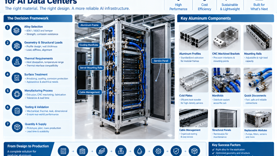
For project teams, the process can be summarized as:
Define the function → Establish performance requirements → Select the alloy and geometry → Choose the manufacturing route → Validate the component → Scale production
Working with an experienced AI infrastructure aluminum supplier can make this process more efficient by connecting engineering requirements with realistic manufacturing capabilities.
At Aluminum4AI, the component development approach can integrate aluminum extrusion, CNC machining, thermal and structural design considerations, surface treatment, and prototype-to-production planning to support custom AI infrastructure projects.
The right aluminum component is not simply a material choice. It is an engineering decision that connects performance, manufacturing, and long-term system reliability.