As AI servers become more powerful and liquid cooling becomes increasingly common, maintenance can no longer be treated as an afterthought.
A liquid-cooled AI rack may contain:
- Cold plates
- Manifolds
- Quick-disconnect couplings
- Cooling hoses
- Pumps
- Sensors
- Power cables
- Network cables
- Aluminum structural frames
- Service panels
- Replaceable modules
All of these components need to work together during normal operation.
But they also need to remain accessible when something needs to be inspected, replaced, cleaned, or repaired.
This makes AI liquid cooling maintenance design an important part of the infrastructure engineering process.
A well-designed system should not only provide good thermal and structural performance.
It should also answer a practical question:
Can a technician safely access and replace the critical components without dismantling the entire rack?
For liquid-cooled server infrastructure, maintainability should be considered from the beginning of the mechanical design.
The objective is not simply to make components removable.
It is to make maintenance predictable, accessible, safe, and repeatable.
Why Maintenance Design Matters in Liquid-Cooled AI Infrastructure
Traditional air-cooled server systems already require regular maintenance.
Liquid-cooled AI infrastructure introduces additional components that may require inspection or replacement.
These include:
- Cooling manifolds
- Quick-disconnects
- Hoses
- Pumps
- Valves
- Seals
- Filters
- Sensors
- Cold plates
- Distribution units
If these components are difficult to access, even a relatively small service task can require substantial downtime.
For a high-density AI environment, this can create operational problems.
A poorly designed rack may require technicians to:
- Remove several servers
- Disconnect multiple cables
- Remove structural panels
- Drain part of the cooling loop
- Reach behind equipment
- Work around tightly packed hoses
- Remove neighboring components
A maintainable rack should minimize these unnecessary steps.
Maintenance Is a Structural Design Requirement
Serviceability should not be added after the rack has already been designed.
The structural system should be designed around the maintenance workflow.
This means considering:
- Where technicians stand
- Where tools can be used
- Where connectors can be reached
- How hoses are routed
- How cables are separated
- Which panels can be removed
- Which components need regular access
- Which components should be replaceable without disturbing others
The resulting structure may include:
- Removable aluminum panels
- Modular brackets
- Accessible mounting rails
- Dedicated hose channels
- Cable-management sections
- Service openings
- Tool-access clearances
The principle is simple:
Design the rack around the service path, not only the installation path.
Map the Maintenance Path Before Designing the Structure
Before selecting profiles, brackets, panels, and connectors, engineers should identify the major maintenance tasks.
For example:
Inspect manifold
↓
Close isolation valve
↓
Disconnect QD
↓
Remove service panel
↓
Replace component
↓
Reconnect
↓
Leak check
↓
Return system to operation
This sequence can reveal accessibility problems before hardware is manufactured.
The same approach can be applied to:
- Pump replacement
- Hose replacement
- Server removal
- Cable replacement
- Sensor replacement
- Filter service
- Cold plate replacement
Identify Replaceable Components
Not every component needs the same level of accessibility.
A useful first step is to classify components by expected service frequency.
Frequently Serviced
- Filters
- Sensors
- Quick-disconnects
- Selected cables
- Service valves
Occasionally Serviced
- Pumps
- Manifolds
- Hoses
- Power modules
Rarely Serviced
- Structural frames
- Fixed brackets
- Permanent cooling channels
Frequently serviced components should generally receive the highest level of accessibility.
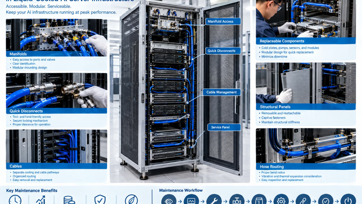
Access to Cooling Manifolds
Manifolds are important components in liquid-cooled AI infrastructure.
They distribute coolant between the main cooling loop and individual servers or cooling branches.
A maintenance-friendly manifold design should consider:
- Port accessibility
- Valve access
- Quick-disconnect access
- Hose routing
- Identification
- Drainage
- Pressure measurement
- Replacement clearance
A manifold hidden behind tightly packed servers may technically function well but become difficult to maintain.
Where practical, manifolds should be positioned in a predictable service zone.
Manifold Mounting Design
The manifold should also be mechanically supported.
A good mounting design can allow the manifold to be:
- Secure during operation
- Accessible during service
- Removed without excessive disassembly
- Reinstalled with consistent alignment
Aluminum brackets can be used to provide a rigid but modular support structure.
For example, a manifold may be attached to an aluminum frame using removable brackets rather than being permanently integrated into a difficult-to-access structural assembly.
Quick-Disconnect Couplings
Quick-disconnect couplings are particularly important in liquid-cooled server maintenance.
They allow cooling circuits to be disconnected without extensive disassembly.
However, the connector itself needs sufficient space.
Maintenance design should provide clearance for:
- Hand access
- Connector engagement
- Connector release
- Locking mechanisms
- Inspection
- Replacement
A QD that is technically reachable but requires excessive force or awkward hand positioning is not necessarily service-friendly.
QD Orientation Matters
The direction in which a quick-disconnect is installed can strongly affect serviceability.
Engineers should consider whether the connector can be accessed:
- From the front
- From the rear
- From the side
- From above
The preferred orientation depends on the rack architecture.
The important point is to establish a consistent maintenance direction.
This can reduce service time and simplify technician training.
Avoiding Connector Congestion
High-density AI racks can contain many cooling connections in a small area.
If several QDs are installed too close together, maintenance becomes difficult.
Potential problems include:
- Limited hand clearance
- Difficulty identifying connections
- Accidental disconnection
- Hose interference
- Difficult inspection
A better design may separate connection points spatially or use dedicated mounting brackets.
The goal is not to minimize physical space at any cost.
It is to optimize usable service density.
Hose Routing for Maintenance
Hose routing is another important part of liquid-cooled server maintenance.
Hoses should be routed with consideration for:
- Bend radius
- Movement
- Connector access
- Replacement
- Thermal expansion
- Vibration
- Adjacent components
A hose that is technically long enough may still be difficult to replace if it is trapped behind other components.
Service loops can sometimes provide additional flexibility.
However, excessive hose length can create unnecessary congestion.
The design should balance operational routing and service access.
Hose Replacement Strategy
A maintainable cooling system should allow a technician to identify how a hose can be replaced before the system is opened.
The design should answer:
- Which components need to be removed?
- Where can the hose be disconnected?
- Is there sufficient slack?
- Can the hose be removed without disturbing adjacent circuits?
- How will the replacement hose be routed?
- How will the connection be checked afterward?
These questions should be addressed during design rather than during the first field repair.
Cable Management and Cooling Maintenance
AI racks contain both cooling infrastructure and large numbers of cables.
These include:
- Power cables
- Network cables
- Sensor cables
- Control cables
- Monitoring connections
Poor cable management can obstruct cooling-system maintenance.
For example, a technician may need to access a manifold but find it surrounded by tightly bundled cables.
A serviceable rack should therefore separate:
Cooling pathways
from
Cable pathways
where practical.
Designing Serviceable Cable Routing
Cable-management structures can include:
- Removable cable trays
- Dedicated cable channels
- Vertical cable organizers
- Modular brackets
- Access panels
The objective is to allow cables to be moved or inspected without completely dismantling the cooling system.
This is especially important in modular AI infrastructure where servers may be replaced independently.
Removable Aluminum Structural Panels
Aluminum panels can provide enclosure and structural functions while still allowing service access.
A maintenance-friendly panel may use:
- Captive fasteners
- Quick-release mechanisms
- Hinges
- Removable brackets
- Standardized fasteners
The specific mechanism depends on the application.
The key requirement is that technicians can remove the panel predictably without damaging the surrounding structure.
Captive Fasteners
Small fasteners can create surprisingly large maintenance problems.
Loose screws can:
- Fall into equipment
- Become lost
- Require additional tools
- Increase service time
Captive fasteners can keep the hardware attached to the panel.
For frequently serviced panels, this can simplify maintenance.
However, the appropriate fastening system should be selected based on structural requirements, vibration conditions, cost, and service frequency.
Tool Access
Serviceability is partly a question of geometry.
A component may be removable in theory but inaccessible with the required tool.
Maintenance design should therefore consider:
- Wrench clearance
- Screwdriver access
- Torque-tool access
- Connector release space
- Hand clearance
For critical service points, engineers can create dedicated tool-access openings.
This is particularly useful around:
- Manifolds
- Mounting brackets
- Valves
- QDs
- Structural fasteners
Front-Service vs. Rear-Service Architecture
Different AI rack designs may use different maintenance directions.
Front-Service
Useful when:
- Server modules are front-accessible
- Cooling connections are positioned at the front
- Operators need minimal rear access
Rear-Service
Useful when:
- Manifolds and hoses are concentrated at the rear
- Cooling distribution is separated from computing modules
Dual-Side Service
Can provide maximum accessibility but requires additional facility space.
There is no universally correct architecture.
The appropriate configuration depends on:
- Rack layout
- Data-center aisle design
- Cooling architecture
- Service procedures
- Equipment density
Modular AI Infrastructure
Modularity can significantly improve serviceability.
A modular AI infrastructure system may divide the rack into:
- Structural module
- Server module
- Cooling module
- Power module
- Cable-management module
Each module can then be serviced or replaced independently.
This reduces the need to disassemble unrelated components.
For example:
Cooling module failure
should ideally not require
complete server-rack disassembly.
Replaceable Cooling Modules
A modular cooling assembly might include:
- Manifold
- QDs
- Hoses
- Valves
- Sensors
- Mounting bracket
Instead of permanently integrating these components into the rack, they can be designed as a replaceable subassembly.
This can reduce maintenance time and simplify spare-parts management.
Service Isolation
Maintenance design should consider how a component can be isolated from the rest of the cooling system.
Potential isolation methods include:
- Shutoff valves
- Isolation valves
- Dedicated branch circuits
- Drain points
- Purge points
The goal is to allow maintenance on one section without unnecessarily affecting the entire cooling loop.
The actual architecture depends on the cooling-system design.
Drainage and Fluid Management
Liquid cooling maintenance inevitably involves fluid management.
A serviceable system should consider:
- Drain points
- Air release
- Fluid collection
- Spill prevention
- Hose disconnection
- Refill procedures
Drainage should be planned into the mechanical architecture.
A system that requires technicians to improvise fluid handling during maintenance creates unnecessary operational risk.
Leak Prevention During Maintenance
Leak prevention is not limited to normal operation.
Maintenance itself can create leak risks.
For example:
- QD not fully engaged
- Damaged O-ring
- Contaminated sealing surface
- Incorrect hose installation
- Loose threaded connection
Therefore, the service procedure should include appropriate verification steps.
Depending on the system, this may include:
- Visual inspection
- Pressure check
- Leak detection
- Flow verification
Designing Around Seals and O-Rings
Seals are relatively small components but can have major consequences for liquid cooling reliability.
Maintenance design should allow technicians to inspect and replace seals where necessary.
The design should minimize:
- Seal damage during assembly
- Misalignment
- Contamination
- Excessive insertion force
Replacement seals should also be clearly specified.
Cold Plate Serviceability
Cold plates may be less frequently replaced than hoses or QDs, but their serviceability should still be considered.
A cold plate may require removal when:
- A server module is replaced
- A cooling component fails
- A seal needs replacement
- A thermal interface needs service
The mounting system should provide controlled:
- Access
- Fastener sequence
- Contact pressure
- Alignment
- Reinstallation
This is particularly important where thermal interface performance depends on mounting pressure and surface contact.
Thermal Interface Replacement
A cold plate may use a thermal interface material between the cooling surface and processor or module.
If the component is removed, the interface may need to be replaced.
The mechanical design should therefore allow:
- Controlled removal
- Surface inspection
- Cleaning
- New TIM installation
- Repeatable mounting
Serviceability and thermal performance are therefore closely connected.
Structural Panels and Service Openings
Structural aluminum panels can also influence maintenance access.
Possible features include:
- Removable covers
- Inspection windows
- Cable openings
- Cooling-access openings
- Service hatches
Openings should be designed carefully so that serviceability does not compromise:
- Structural stiffness
- EMI requirements
- Airflow
- Protection
- Safety
This is where mechanical engineering becomes a system-level design problem.
Maintaining Structural Stiffness
Adding large service openings can reduce structural stiffness.
Therefore, removable panels and access holes may require:
- Reinforced edges
- Structural frames
- Additional ribs
- Local brackets
The objective is to provide access without compromising the structural requirements validated during mechanical testing.
Serviceability and Airflow
In hybrid air/liquid-cooled AI infrastructure, maintenance openings can also influence airflow.
For example, removing a panel may change:
- Airflow distribution
- Fan pressure
- Cooling performance
The service architecture should therefore be evaluated in both normal operating and maintenance configurations.
Serviceability and Thermal Expansion
Cooling structures can experience temperature changes.
Hoses, manifolds, aluminum frames, and other components may expand differently.
Maintenance design should provide sufficient flexibility to accommodate these movements without placing excessive loads on connectors.
This is particularly important around:
- QDs
- Manifold connections
- Rigid pipe sections
- Cold plates
A serviceable connection should also remain mechanically stable throughout the operating temperature range.
Sensor Accessibility
Liquid-cooled AI systems may use sensors for:
- Temperature
- Pressure
- Flow
- Leakage
Sensors can eventually require inspection or replacement.
Therefore, sensor locations should provide:
- Physical access
- Connector access
- Cable routing
- Identification
- Replacement clearance
A sensor buried inside a sealed structural assembly may be difficult to maintain even if its original installation is straightforward.
Designing for Fault Isolation
Good maintenance design helps technicians locate problems quickly.
For example, if a cooling branch shows abnormal flow, the system should make it practical to determine whether the issue is associated with:
- Pump
- Manifold
- Hose
- QD
- Cold plate
- Valve
- Sensor
Modular branches and accessible test points can simplify fault isolation.
This reduces unnecessary component replacement.
Serviceability and Monitoring
Mechanical serviceability works together with digital monitoring.
Sensors can identify:
- Increasing temperature
- Reduced flow
- Pressure abnormalities
- Potential leakage
The physical design should then allow technicians to access the suspected component.
This creates a useful chain:
Monitoring → Diagnosis → Physical Access → Component Replacement → Verification
The best service architecture connects these steps together.
Designing for Minimal Downtime
The purpose of maintenance design is ultimately to reduce downtime.
One useful way to evaluate a design is to estimate:
Time to Diagnose + Time to Access + Time to Replace + Time to Verify
A component may be inexpensive but still create significant operational cost if it takes hours to access.
Conversely, a slightly more sophisticated modular structure may reduce service time substantially.
Therefore, serviceability can have direct lifecycle value.
Maintenance Time as a Design Metric
Engineering teams can define service targets such as:
- Maximum time to access a manifold
- Maximum time to replace a hose
- Maximum time to replace a sensor
- Maximum time to remove a server
- Maximum number of components that must be removed
These metrics can then be used during design reviews.
This transforms “easy to maintain” from a subjective statement into something that can be evaluated.
A Practical Serviceability Review
Before releasing a liquid-cooled AI rack design, engineers can conduct a structured review.
Ask:
Can the technician reach it?
Can the required tool reach it?
Can the component be removed?
Can it be removed without disturbing unrelated components?
Can the cooling circuit be isolated?
Can fluid be controlled during service?
Can the replacement component be installed in the correct orientation?
Can the system be tested after replacement?
If the answer to several of these questions is no, the design may need additional service-access features.
Design for Maintenance From the Prototype Stage
Serviceability should be tested during prototype validation.
A technician or engineer can simulate tasks such as:
- Server replacement
- QD disconnection
- Hose replacement
- Manifold replacement
- Sensor replacement
- Panel removal
- Cable replacement
The team can then record:
- Number of steps
- Required tools
- Access difficulty
- Service time
- Components accidentally disturbed
This creates real evidence for design improvement.
Maintenance Validation During Pilot Production
Pilot production provides another opportunity to validate serviceability.
Production-intent hardware should be used where possible because small changes in:
- Brackets
- Fasteners
- Cable routing
- Hose length
- Panel geometry
can change the actual maintenance experience.
The objective is to verify that the production configuration remains as serviceable as the prototype.
Common Maintenance Design Mistakes
1. Designing Only for Installation
A component that is easy to install may be difficult to replace.
2. Hiding the Manifold
Compact placement can create major service problems.
3. Overcrowding QDs
Connectors need practical hand and tool clearance.
4. Ignoring Hose Bend Radius
Tightly routed hoses can be difficult to replace.
5. Mixing Cooling and Cable Pathways
Cable congestion can block maintenance access.
6. Using Too Many Permanent Fasteners
Frequently serviced panels should not require unnecessary disassembly.
7. Ignoring Fluid Drainage
Maintenance needs a defined fluid-management strategy.
8. Forgetting Sensor Replacement
Monitoring components also need physical access.
9. Making Access Panels Too Large Without Reinforcement
Serviceability should not compromise structural stiffness.
10. Never Testing the Maintenance Procedure
A design review cannot fully replace hands-on service validation.
A Practical AI Liquid Cooling Maintenance Workflow
A service-oriented development process can follow these steps.
Step 1 — Identify Serviceable Components
List all components likely to require replacement or inspection.
Step 2 — Define Service Frequency
Classify components as frequent, occasional, or low-frequency service items.
Step 3 — Map the Service Path
Define how the technician reaches each component.
Step 4 — Design Access
Provide appropriate:
- Panels
- Brackets
- Clearances
- Service openings
- Tool access
Step 5 — Design Isolation
Provide valves, branch circuits, drain points, or other appropriate service features.
Step 6 — Separate Cooling and Cable Paths
Reduce interference between systems.
Step 7 — Validate the Service Procedure
Perform hands-on maintenance simulations.
Step 8 — Measure Service Time
Identify unnecessary steps.
Step 9 — Validate Structural and Thermal Performance
Ensure service features do not compromise the original design.
Step 10 — Standardize the Maintenance Architecture
Use repeatable modules and interfaces across the product family where practical.
Serviceability Matrix for Liquid-Cooled AI Infrastructure
| Component | Access Requirement | Typical Service Action | Key Design Consideration |
|---|---|---|---|
| Manifold | High | Inspect / replace | Port and valve access |
| Quick-disconnect | High | Disconnect / replace | Hand and tool clearance |
| Hose | High | Replace | Bend radius and routing |
| Sensor | Medium–High | Inspect / replace | Connector access |
| Pump | Medium–High | Replace | Modular mounting |
| Cold plate | Medium | Replace / service | Controlled mounting |
| Cable | High | Replace / reroute | Separate cable path |
| Structural panel | High | Remove / reinstall | Captive fasteners |
| Aluminum bracket | Medium | Inspect / replace | Modular mounting |
| Valve | High | Operate / replace | Service clearance |
The exact service architecture should be adapted to the cooling system and operating environment.
Designing Modular Aluminum Infrastructure for Serviceability
Aluminum extrusion can be particularly useful for modular AI infrastructure.
Extruded profiles can provide:
- Structural support
- Mounting channels
- Cable routing
- Cooling integration
- Panel attachment
Combined with CNC-machined brackets and removable panels, an aluminum frame can create a flexible service architecture.
For example:
Extruded aluminum frame
Modular manifold bracket
Accessible QDs
Dedicated hose routing
Removable service panel
can create a maintainable liquid-cooled rack without making every component permanently integrated.
Balancing Compactness and Serviceability
AI infrastructure naturally pushes toward higher density.
But maximum density is not always the same as optimal design.
Reducing every clearance may improve packaging efficiency while making maintenance much harder.
A better optimization considers:
Equipment density + cooling performance + structural performance + service access
The best design is often the one that achieves the required density while preserving predictable maintenance paths.
As liquid cooling becomes more important in high-density AI infrastructure, serviceability should become part of the mechanical design rather than an afterthought.
Effective AI liquid cooling maintenance design should provide practical access to:
- Manifolds
- Quick-disconnect couplings
- Hoses
- Cables
- Sensors
- Valves
- Cold plates
- Structural panels
- Replaceable modules
The most important principle is simple:
A component is not truly serviceable just because it can technically be removed.
It should be accessible with the required tools, removable without unnecessary disassembly, replaceable without disturbing unrelated systems, and testable after maintenance.
For liquid cooled server maintenance, this means designing around the complete service workflow:
Detect → Diagnose → Access → Isolate → Remove → Replace → Reconnect → Test → Restore
For AI rack serviceability, modular aluminum structures can provide an effective foundation for removable panels, accessible brackets, dedicated cable and hose pathways, and replaceable cooling modules.
For modular AI infrastructure, the long-term objective is to make maintenance predictable rather than improvised.
A well-designed AI rack should therefore be evaluated not only by how well it performs on day one, but also by how easily an engineer can maintain it years later.
Good infrastructure design supports the hardware.
Better infrastructure design also supports the people who maintain it.