


Aluminum is widely used in AI infrastructure because of its combination of thermal conductivity, low density, manufacturability, corrosion resistance, and structural performance.
However, stating that an aluminum component has good thermal conductivity does not prove that it will perform well inside an AI cooling system.
A material property is only one part of the thermal path.
The actual thermal performance of an AI infrastructure component depends on the complete system:
Heat source → interface → aluminum component → cooling structure → coolant or airflow → heat rejection
This is why aluminum thermal testing for AI infrastructure should focus on actual thermal behavior rather than relying only on material datasheets.
For heat sinks, heat spreaders, cold plates, cooling channels, and aluminum structural thermal components, testing should answer several practical questions:
- How much heat can the component handle?
- What temperature does the heat source reach?
- How much temperature difference exists across the component?
- How effectively is heat transferred to the cooling medium?
- How much pressure drop does the cooling structure create?
- Does performance remain stable under different operating conditions?
- Does the manufactured component perform consistently from one production batch to another?
The objective is not simply to demonstrate that aluminum conducts heat.
The objective is to determine whether the finished component performs as required inside the intended AI infrastructure system.
Why Thermal Conductivity Alone Is Not Enough
Aluminum alloy datasheets commonly provide a thermal conductivity value.
This is useful information.
But thermal conductivity describes a material property under defined conditions. It does not directly describe the thermal performance of a finished AI cooling component.
Consider two aluminum cold plates made from the same alloy.
They may have identical nominal thermal conductivity but significantly different thermal performance because of differences in:
- Channel geometry
- Wall thickness
- Contact area
- Surface flatness
- Thermal interface material
- Coolant flow
- Pressure drop
- Port configuration
- Manufacturing tolerances
- Heat-source distribution
The same principle applies to heat sinks.
A heat sink made from thermally conductive aluminum can still perform poorly if:
- The base is too thick
- The thermal interface is poor
- Fin geometry is unsuitable
- Airflow is restricted
- Contact pressure is inconsistent
- The heat source is poorly coupled to the base
Therefore:
Material conductivity is an input. Thermal performance is an engineering result.
What Should Be Tested?
The appropriate thermal test program depends on the component.
For AI infrastructure aluminum components, common testing categories include:
- Thermal resistance
- Temperature distribution
- Heat dissipation capability
- Thermal interface performance
- Coolant flow and pressure drop
- Temperature uniformity
- Thermal cycling
- Steady-state performance
- Transient thermal response
- Performance consistency between production parts
Not every component requires every test.
The test plan should be connected to the actual application.
Thermal Testing of Different Aluminum Components
Different components require different testing strategies.
| Component | Key Thermal Tests |
|---|---|
| Heat sink | Temperature rise, thermal resistance, airflow |
| Heat spreader | Temperature distribution, spreading resistance |
| Cold plate | Thermal resistance, coolant flow, pressure drop |
| Cooling channel | Heat transfer, flow, temperature distribution |
| Thermal block | Heat dissipation, interface temperature |
| AI server chassis | Local thermal behavior, heat spreading |
| Edge AI enclosure | Internal temperature, passive/forced cooling |
| Integrated thermal structure | System-level thermal performance |
This is why there is no single universal thermal test for aluminum AI infrastructure.
1. Thermal Resistance Testing
Thermal resistance is one of the most useful parameters for evaluating a cooling component.
Lower thermal resistance generally indicates that less temperature rise occurs for a given heat load under the defined test conditions.
For example, a cold plate can be evaluated by measuring the temperature difference between the heat source and the coolant under a controlled heat load.
However, the exact definition of thermal resistance must be clearly stated.
The result depends on:
- Measurement locations
- Heat load
- Coolant temperature
- Flow rate
- Interface material
- Mounting pressure
- Ambient conditions
A thermal-resistance number without test conditions can therefore be difficult to interpret.
2. Heat Dissipation Testing
For heat sinks and other air-cooled aluminum components, testing should determine how effectively the component removes heat under defined airflow conditions.
Important variables may include:
- Heat input
- Ambient temperature
- Air temperature
- Airflow rate
- Air velocity
- Fan operating point
- Heat sink temperature
- Base temperature
- Outlet air temperature
The test should reproduce the intended operating environment as closely as practical.
A heat sink that performs well at one airflow rate may behave differently when airflow is restricted.
This is particularly important in dense AI server environments where available airflow can be limited.
3. Temperature Distribution
Average temperature is not always enough.
An AI cooling component can have significant temperature differences across its surface.
Thermal imaging or multiple temperature sensors can help reveal:
- Hot spots
- Uneven heat spreading
- Channel imbalance
- Poor thermal interfaces
- Localized thermal resistance
For example, a heat spreader may show a high-temperature region directly above the processor and lower temperatures farther away.
The shape of this temperature distribution can provide useful information about the component’s actual thermal behavior.
Thermal Imaging for AI Cooling Components
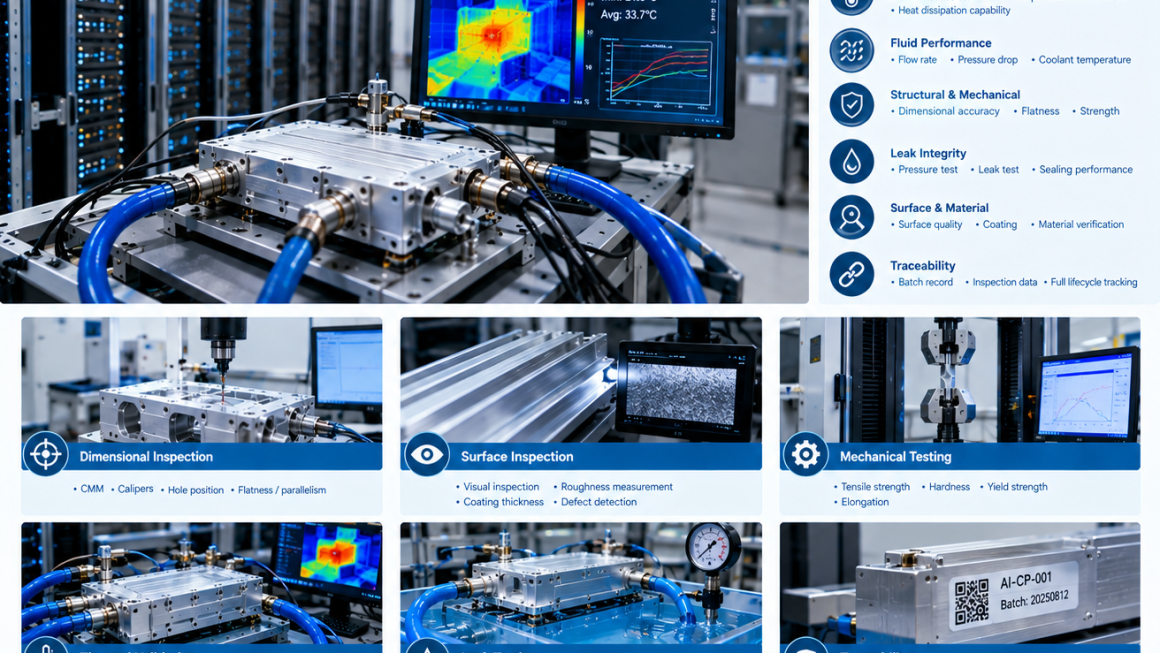
Infrared thermal imaging can be useful for visualizing temperature distribution.
It can help identify:
- Local hot spots
- Uneven cooling
- Poor contact
- Flow imbalance
- Thermal gradients
However, infrared measurements require appropriate surface emissivity and test conditions.
Highly reflective bare aluminum surfaces can complicate infrared measurement.
Therefore, thermal imaging should be properly calibrated or combined with contact sensors when accurate temperature measurements are required.
The objective is to obtain reliable temperature data, not simply attractive thermal images.
4. Thermal Interface Testing
The interface between the heat source and aluminum component can dominate the thermal path.
Possible interface materials include:
- Thermal grease
- Thermal pads
- Phase-change materials
- Graphite-based interfaces
- Other thermal interface materials
Testing should consider:
- Interface thickness
- Contact pressure
- Surface flatness
- Surface roughness
- TIM properties
- Mounting method
Two identical aluminum heat spreaders can produce different results if their mounting conditions are different.
Therefore, thermal testing should control the interface conditions carefully.
Why Flatness Matters
A cold plate or heat spreader may have excellent thermal conductivity but still show poor performance if the contact surface is not adequately controlled.
A non-flat interface can create:
- Air gaps
- Uneven TIM thickness
- Localized thermal resistance
- Uneven contact pressure
For precision cooling components, flatness should therefore be evaluated together with thermal performance.
This is an important example of why AI cooling component testing should combine dimensional and functional measurements.
5. Cold Plate Testing
Cold plates are among the most important thermal components in liquid-cooled AI infrastructure.
A meaningful cold plate test should consider both thermal and fluid performance.
Typical parameters include:
- Heat load
- Coolant inlet temperature
- Coolant outlet temperature
- Flow rate
- Pressure drop
- Surface temperature
- Heat-source temperature
- Thermal resistance
The test setup should represent the intended operating conditions.
A cold plate that provides excellent heat transfer at an extremely high flow rate may not be suitable if the resulting pressure drop is excessive.
This creates an important engineering trade-off:
Thermal performance must be evaluated together with hydraulic performance.
6. Coolant Flow Rate
Coolant flow is a critical variable in liquid cooling.
As flow conditions change, heat transfer behavior can also change.
Testing may therefore evaluate several flow points rather than a single operating condition.
For example:
Low flow → nominal flow → high flow
This helps establish the operating range of the cooling component.
The resulting data can be used to identify:
- Thermal performance
- Pressure drop
- Flow sensitivity
- Operating limits
The goal is to understand the component rather than simply produce one favorable test number.
7. Pressure Drop Testing
Pressure drop is not strictly a thermal parameter, but it is essential to liquid-cooling performance.
A cooling channel can transfer heat effectively while creating excessive hydraulic resistance.
Pressure drop testing can therefore help determine whether the cooling component is practical for integration into the larger cooling loop.
Typical measurements include:
- Inlet pressure
- Outlet pressure
- Flow rate
- Coolant temperature
The resulting pressure-drop curve can be evaluated together with thermal performance.
This creates a more complete picture of the component.
Thermal Performance vs. Pressure Drop
For liquid cooling components, engineers often need to balance two objectives:
Higher heat transfer
and
Acceptable hydraulic resistance
Increasing channel complexity may improve heat transfer but also increase pressure drop.
Reducing channel size may increase surface interaction but create greater flow resistance.
Therefore, thermal testing should not be isolated from fluid testing.
A useful test program evaluates both.
8. Heat Spreading Testing
Heat spreaders perform a different function from cold plates.
Their primary purpose is often to distribute heat across a larger area.
This can reduce localized hot spots and improve the effectiveness of the downstream cooling system.
Testing may examine:
- Heat-source temperature
- Surface temperature distribution
- Temperature gradient
- Spreading area
- Steady-state temperature
A thermal camera or distributed temperature sensors can help visualize how heat moves across the aluminum structure.
This can be particularly useful for:
- AI processor heat spreaders
- Power electronics
- Compact edge AI systems
- Battery-related thermal structures
9. Steady-State Thermal Testing
Steady-state testing evaluates the component after temperatures have stabilized under a defined heat load.
This type of test is useful for determining:
- Stable operating temperature
- Thermal resistance
- Temperature distribution
- Cooling capacity
For example, an aluminum cold plate can be tested under a constant heat load until the heat-source temperature and coolant temperatures reach a stable condition.
The test should define what qualifies as thermal equilibrium.
Without a consistent stabilization criterion, results from different tests may not be directly comparable.
10. Transient Thermal Testing
AI processors and power electronics do not always operate at constant power.
Their heat output can change rapidly.
Transient testing can therefore be useful.
A test may simulate:
Low load → high load → low load
or another application-specific power profile.
This helps evaluate:
- Temperature response
- Thermal time constant
- Peak temperature
- Cooling recovery
- Thermal lag
Transient behavior can be particularly relevant to AI systems with rapidly changing workloads.
Thermal Cycling
Repeated temperature changes can place mechanical stress on aluminum components and interfaces.
Thermal cycling may involve:
Low temperature → high temperature → low temperature
repeated for a defined number of cycles.
This can help evaluate:
- Thermal expansion
- Interface stability
- Sealing performance
- Joint reliability
- Coating behavior
- Long-term dimensional stability
For components combining aluminum with copper, polymers, seals, or other materials, differential thermal expansion may also become important.
11. Thermal Expansion and Mechanical Stability
Aluminum has a relatively high coefficient of thermal expansion compared with some other engineering materials.
As temperature changes, an aluminum component changes dimensions.
In a cooling system, this can affect:
- Mounting interfaces
- Seals
- Fasteners
- Cold plate contact
- Hose connections
- Manifolds
Thermal testing should therefore consider not only temperature but also mechanical behavior where the application requires it.
A component that performs well thermally at one temperature may need additional validation across its full operating temperature range.
12. Temperature Uniformity
Temperature uniformity can be important for certain cooling structures.
For a cold plate, uneven temperature distribution may indicate:
- Uneven coolant distribution
- Poor channel design
- Localized heat-transfer limitations
- Uneven contact
- Manufacturing variation
For a heat spreader, temperature gradients can reveal whether heat is being distributed effectively.
Therefore, thermal testing should often include multiple measurement points rather than relying on a single sensor.
13. Thermal Testing of Extruded Aluminum Cooling Channels
Extrusion can be used to create aluminum cooling channels integrated into structural profiles.
These components may combine:
- Structural support
- Coolant routing
- Heat spreading
- Mounting interfaces
Testing should evaluate both thermal and structural functions.
Relevant measurements may include:
- Coolant flow
- Pressure drop
- Inlet temperature
- Outlet temperature
- Surface temperature
- Heat load
- Channel dimensions
This is particularly important because small variations in channel geometry can influence both fluid and thermal performance.
14. Manufacturing Variation and Thermal Performance
A prototype may perform well under laboratory conditions.
But production components can vary slightly.
Potential sources include:
- Extrusion dimensional variation
- CNC machining variation
- Surface roughness
- Flatness
- Channel dimensions
- Port geometry
- Material variation
- Assembly pressure
The question for production is therefore:
Can the manufacturing process consistently produce the validated thermal performance?
This connects thermal validation with quality control.
Thermal Validation During Pilot Production
Pilot production is an important stage for thermal components.
Instead of testing only the first prototype, manufacturers can select representative pilot-production parts.
Testing can then determine whether thermal performance remains within the expected range.
For example:
Prototype thermal performance
↓
Pilot batch thermal performance
↓
Production specification
↓
Ongoing production monitoring
This approach helps prevent a situation where a prototype meets the requirement but mass-produced components behave differently.
Thermal Testing and Production Sampling
Not every production component necessarily needs a full thermal test.
A practical quality system may combine:
100% Inspection
For selected critical characteristics such as:
- Dimensions
- Leak integrity
- Certain assembly interfaces
Sampling Thermal Tests
For representative production batches.
Periodic Full Validation
After:
- Tooling changes
- Material changes
- Process changes
- Supplier changes
- Major engineering revisions
The appropriate strategy depends on the component’s risk and customer requirements.
Test Conditions Must Be Clearly Defined
Thermal data without test conditions can be misleading.
A meaningful test report should identify conditions such as:
- Heat input
- Ambient temperature
- Coolant type
- Coolant temperature
- Flow rate
- Airflow
- Mounting pressure
- TIM type and thickness
- Measurement locations
- Test duration
- Stabilization criteria
For a cold plate, for example, simply reporting:
“Thermal resistance = X”
does not provide enough information to understand the result.
The complete test condition is part of the result.
Thermal Test Equipment
Depending on the component, thermal testing may use:
- Controlled heat sources
- Thermocouples
- RTDs
- Thermal cameras
- Flow meters
- Pressure sensors
- Data acquisition systems
- Environmental chambers
- Cooling loops
- Power supplies
For AI cooling components, the test equipment should be selected according to the actual operating conditions.
A laboratory test does not need to reproduce every detail of a data center.
But it should reproduce the critical thermal and mechanical boundary conditions relevant to the component.
Thermal Testing of AI Server Components
AI server components may experience different heat loads and cooling conditions depending on system architecture.
A test program may therefore simulate:
- Processor heat loads
- GPU heat loads
- Power electronics
- Localized hot spots
- Rack-level thermal conditions
For example, a heat spreader may be tested with a controlled heat source representing the processor contact area.
A cold plate may be tested with a controlled heater and liquid cooling loop.
This creates a repeatable environment for comparing different designs.
Comparing Different Aluminum Designs
Thermal testing becomes especially valuable during design development.
Suppose an engineering team has three cooling-channel designs.
Instead of assuming that the most complex design will perform best, the designs can be experimentally compared.
Measurements might include:
| Parameter | Design A | Design B | Design C |
|---|---|---|---|
| Heat load | Defined | Defined | Defined |
| Thermal resistance | Measured | Measured | Measured |
| Flow rate | Measured | Measured | Measured |
| Pressure drop | Measured | Measured | Measured |
| Maximum temperature | Measured | Measured | Measured |
| Temperature uniformity | Measured | Measured | Measured |
This approach turns thermal design from assumption into engineering evidence.
Simulation and Physical Testing
Thermal simulation can be useful during the design stage.
Computational models can help evaluate:
- Temperature distribution
- Heat flow
- Channel geometry
- Fin geometry
- Flow behavior
- Thermal gradients
However, simulation should not automatically replace physical validation.
Real components contain:
- Manufacturing tolerances
- Surface conditions
- Assembly variation
- Material interfaces
- Actual coolant behavior
A practical development process is therefore:
Simulation → Prototype → Thermal Test → Design Optimization → Pilot Validation
The test results can then be used to improve the simulation model.
Correlating Simulation With Testing
When simulation and physical testing produce different results, the difference itself can be useful.
Possible causes include:
- Incorrect boundary conditions
- Material-property assumptions
- Contact resistance
- TIM behavior
- Manufacturing variation
- Coolant properties
- Sensor placement
Rather than simply choosing one result, engineers can investigate the difference and improve the model.
This creates a stronger engineering process.
Thermal Testing and Surface Treatment
Surface treatment can affect thermal performance depending on the component.
For example, a coating or anodized layer may change surface characteristics.
The impact may be small or significant depending on the heat-transfer mechanism.
For air-cooled heat sinks, surface characteristics can influence radiation and environmental durability.
For precision thermal interfaces, excessive coating thickness may affect contact conditions.
Therefore, thermal validation should represent the final production surface condition whenever possible.
Testing Aluminum-Copper Thermal Interfaces
AI cooling systems may combine aluminum structures with copper heat-transfer components.
Testing should consider the complete interface rather than evaluating the metals independently.
Relevant factors may include:
- Contact resistance
- Surface condition
- Interface material
- Mounting pressure
- Thermal expansion
- Corrosion protection
A copper component with excellent conductivity does not automatically guarantee excellent system-level thermal performance if the interface between copper and aluminum is poorly designed.
Environmental Thermal Testing
Some AI infrastructure is installed outside controlled data-center environments.
Edge AI systems and outdoor energy infrastructure may experience:
- High ambient temperature
- Low ambient temperature
- Solar exposure
- Dust
- Humidity
- Temperature cycling
For these applications, thermal testing may need to include environmental conditions.
An aluminum enclosure that performs well in a laboratory at 23°C may behave differently at a high outdoor ambient temperature.
Therefore, the test environment should reflect the intended application.
Thermal Testing for Passive Cooling
Not every AI infrastructure component uses active liquid cooling.
Passive or natural-convection designs may rely on:
- Aluminum heat sinks
- Large surface areas
- Heat spreading
- Natural airflow
- Radiation
Testing may therefore focus on:
- Ambient temperature
- Surface temperature
- Heat load
- Temperature rise
- Natural convection conditions
Passive cooling should be tested under realistic environmental conditions because airflow patterns can strongly affect performance.
What a Useful Thermal Test Report Should Contain
A professional thermal test report should provide enough information for another engineer to understand and reproduce the test.
A useful report may include:
Component Information
- Part number
- Revision
- Material
- Manufacturing process
Test Setup
- Heat source
- Cooling method
- Sensors
- Instrumentation
Test Conditions
- Heat load
- Ambient temperature
- Coolant temperature
- Flow rate
- Airflow
- Mounting conditions
Results
- Maximum temperature
- Average temperature
- Temperature distribution
- Thermal resistance
- Pressure drop where applicable
- Flow rate
Conclusions
- Whether the component meets the defined requirement
- Any observed limitations
- Recommended operating range
This makes the test data useful for both engineering and production decisions.
Common Thermal Testing Mistakes
1. Reporting Only Thermal Conductivity
Material conductivity does not represent complete component performance.
2. Using Uncontrolled Test Conditions
Changing flow rate, heat load, or interface conditions can make results difficult to compare.
3. Measuring Only One Temperature
A single sensor may miss hot spots or temperature gradients.
4. Ignoring Pressure Drop
Liquid cooling performance should consider both heat transfer and hydraulic resistance.
5. Testing the Prototype but Not the Production Part
Manufacturing variation can change thermal performance.
6. Ignoring the Thermal Interface
Contact resistance can dominate the total thermal path.
7. Using Thermal Images Without Proper Calibration
Reflective aluminum surfaces can complicate infrared measurements.
8. Over-Optimizing One Metric
Maximum heat transfer is not necessarily the only design objective.
A Practical Thermal Testing Workflow
A structured thermal validation process can follow these steps.
Step 1 — Define the Thermal Requirement
Determine:
- Heat load
- Maximum temperature
- Operating temperature
- Required thermal resistance
- Cooling method
Step 2 — Define Boundary Conditions
Specify:
- Ambient temperature
- Coolant
- Flow rate
- Airflow
- Interface conditions
Step 3 — Select Measurement Points
Identify:
- Heat-source temperature
- Component temperature
- Coolant inlet/outlet
- Ambient temperature
- Hot spots
Step 4 — Test the Prototype
Measure actual thermal performance.
Step 5 — Compare With Simulation
Identify differences and refine the model.
Step 6 — Optimize the Design
Adjust:
- Channel geometry
- Fin geometry
- Base thickness
- Contact interface
- Flow path
Step 7 — Validate Pilot Production
Confirm that production-intent components reproduce the expected performance.
Step 8 — Establish Production Controls
Define inspection and sampling requirements for ongoing manufacturing.
From Material Property to System Performance
The most important distinction in aluminum thermal testing is the difference between material property and component performance.
Thermal conductivity tells engineers how readily heat can move through a material.
Thermal testing tells engineers what actually happens when that material is manufactured into a real component and placed into a real thermal system.
For example:
Aluminum alloy
↓
Heat spreader geometry
↓
Thermal interface
↓
Cooling method
↓
Heat load
↓
Measured temperature
↓
System thermal performance
Every stage can influence the final result.
This is why a good thermal test program should evaluate the complete thermal path.
Aluminum remains an important material for AI infrastructure because it offers a useful combination of thermal performance, low weight, structural capability, manufacturability, and cost.
But high thermal conductivity alone is not a sufficient specification for an AI cooling component.
For aluminum thermal testing for AI infrastructure, engineers should evaluate the finished component under defined and repeatable conditions.
Depending on the application, this may include:
- Thermal resistance
- Heat dissipation
- Temperature distribution
- Thermal interface performance
- Coolant flow
- Pressure drop
- Temperature uniformity
- Transient response
- Thermal cycling
- Thermal expansion
- Production consistency
For cold plates, testing should combine thermal and hydraulic performance.
For heat sinks, airflow and temperature rise are critical.
For heat spreaders, temperature distribution and spreading behavior matter.
For integrated cooling structures, thermal, mechanical, and fluid performance may need to be evaluated together.
The most useful thermal test is therefore not the one that produces the highest number.
It is the one that answers the engineering question that matters.
How does this aluminum component actually perform under the conditions where it will be used?
That is the foundation of reliable AI cooling component testing, aluminum heat dissipation testing, and cold plate testing.
Ultimately, the thermal validation chain should be:
Material Data → Simulation → Prototype → Thermal Test → Design Optimization → Pilot Validation → Production Control
The goal is not simply to prove that aluminum can conduct heat.
The goal is to prove that the finished aluminum component can manage heat reliably inside the AI infrastructure system.