Developing an aluminum component for AI infrastructure is only the beginning.
A prototype may demonstrate that a server frame fits, a cold plate transfers heat, a manifold connects correctly, or an enclosure provides the required structural protection. But moving from a successful prototype to stable production introduces a different set of engineering and manufacturing challenges.
Production requires more than making the same part repeatedly.
It requires a controlled process that delivers consistent dimensions, reliable material properties, predictable thermal and mechanical performance, manageable production costs, and repeatable quality.
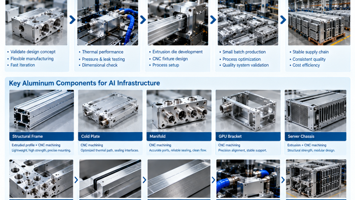
For aluminum AI infrastructure prototype to production, the transition can be viewed as a structured manufacturing path:
Prototype → Validation → Design Optimization → Tooling → Pilot Production → Process Qualification → Mass Production
Each stage has a different objective.
The goal is not to rush from prototype to mass production. The goal is to remove uncertainty step by step until the component is ready for repeatable manufacturing.
Why Scaling AI Aluminum Components Is Different
AI infrastructure components often combine several engineering functions.
An aluminum component may simultaneously provide:
- Structural support
- Thermal conduction
- Cooling channel integration
- Precision mounting
- Cable management
- Sealing
- Electrical or mechanical interfaces
- Environmental protection
This makes manufacturing scale-up more complicated than simply increasing the quantity of an existing prototype.
A prototype can sometimes tolerate:
- Manual adjustments
- Low-volume CNC machining
- Extra finishing
- Hand fitting
- Individual inspection
- Temporary fixtures
Mass production cannot rely on these methods indefinitely.
Production needs defined processes, controlled tolerances, repeatable fixtures, documented inspection criteria, and stable material and surface-treatment specifications.
This is why AI hardware manufacturing should be considered from the beginning of product development.
Stage 1: Prototype Development
The first stage is usually focused on proving the engineering concept.
At this point, manufacturing flexibility is often more important than production efficiency.
CNC machining is particularly useful for prototypes because engineers can modify the geometry without committing to production tooling.
Prototype aluminum components may include:
- AI server brackets
- Cooling blocks
- Cold plates
- Heat sinks
- Manifolds
- Structural frames
- Chassis panels
- Mounting components
- Edge AI enclosures
The prototype should answer basic engineering questions.
Does it fit?
The component must physically integrate with surrounding hardware.
Does it function?
Cooling, structural, sealing, and mounting requirements need to be verified.
Can it be assembled?
Fasteners, connectors, hoses, cables, and service access should be checked.
Can it be manufactured?
The prototype should reveal features that may become difficult or expensive during production.
Prototype Manufacturing Methods
Different prototype components may use different manufacturing processes.
Common options include:
- CNC machining
- Aluminum extrusion + CNC
- Sheet metal fabrication
- 3D printing for non-metallic mockups
- Casting for selected geometries
- Hybrid manufacturing
For aluminum AI infrastructure components, CNC machining and extrusion + CNC are particularly useful because they can produce functional metal parts rather than only visual prototypes.
A prototype should ideally represent the final production material and important manufacturing characteristics whenever practical.
For example, a plastic mockup may verify physical dimensions, but it cannot fully validate the behavior of an aluminum cold plate or structural frame.
Stage 2: Engineering Validation
A prototype is not automatically a production-ready product.
The next step is validation.
Validation should be based on the actual function of the component.
For a structural aluminum component, testing may include:
- Static load
- Deflection
- Fastener performance
- Vibration
- Assembly repeatability
For a cooling component:
- Thermal performance
- Flow behavior
- Pressure testing
- Leak testing
- Thermal cycling
For an enclosure:
- Structural integrity
- Environmental protection
- Thermal behavior
- Assembly
- Serviceability
The purpose is to identify whether the design works under realistic operating conditions.
Design Validation vs. Production Validation
These two stages should be distinguished.
Design Validation
The main question is:
Does the component design meet its functional requirements?
Examples include:
- Required load capacity
- Required thermal performance
- Required flow characteristics
- Required dimensional relationships
- Required sealing performance
Production Validation
The question becomes:
Can the manufacturing process produce the validated design consistently?
A design can work perfectly in one prototype while still being difficult to manufacture repeatedly.
This distinction becomes increasingly important as production volume increases.
Stage 3: Design for Manufacturing
After the initial validation, the design should be reviewed from a manufacturing perspective.
This is where DFM — Design for Manufacturing — becomes important.
The engineering team should examine:
- Part geometry
- Material selection
- Extrusion feasibility
- CNC accessibility
- Tool access
- Tolerances
- Wall thickness
- Fastener strategy
- Surface treatment
- Inspection requirements
- Assembly sequence
A feature that is technically possible may not necessarily be appropriate for mass production.
For example, a very deep CNC pocket might work on a prototype but require excessive machining time during production.
A complex extrusion profile might reduce CNC work but require expensive tooling.
The objective is to find the appropriate balance.
Stage 4: Choosing the Production Process
At this stage, the manufacturing route becomes more clearly defined.
Possible routes include:
CNC Machining
Suitable for:
- Complex components
- Low-to-medium volumes
- Precision interfaces
- Customized cooling blocks
- Prototypes and pilot production
Aluminum Extrusion
Suitable for:
- Long profiles
- Repeated cross-sections
- Structural frames
- Cooling channels
- Heat sink profiles
- Rails and channels
Extrusion + CNC
Suitable when a component contains both:
- A continuous base geometry
and
- Localized precision features
This hybrid approach can be particularly useful for AI infrastructure.
Other Processes
Depending on geometry and volume, casting, forging, sheet metal fabrication, or other processes may also become appropriate.
The correct choice depends on the actual component.
Stage 5: Production Tooling
For extruded aluminum components, production tooling usually becomes an important consideration.
An extrusion die defines the basic profile geometry.
Before investing in a production die, engineers should confirm:
- Profile dimensions
- Wall thickness
- Internal cavities
- Structural requirements
- Cooling channel geometry
- Mounting features
- CNC access
- Surface treatment
- Final assembly
Tooling should be based on a sufficiently mature design.
Changing a critical profile after tooling has been completed can create additional cost and schedule impact.
This is why validation should occur before final production tooling whenever practical.
Extrusion Die Design for AI Components
A well-designed extrusion profile can reduce downstream manufacturing complexity.
The profile may incorporate:
- Structural ribs
- Hollow sections
- Cooling channels
- Mounting slots
- Fastener channels
- Cable routing paths
- Heat-spreading surfaces
However, maximum integration is not always the goal.
An overly complicated profile can create:
- More difficult extrusion
- Higher tooling complexity
- More difficult dimensional control
- Greater material consumption
- More challenging CNC operations
The profile should therefore be designed around both engineering function and manufacturing feasibility.
CNC Tooling and Fixtures
CNC production also requires more than the machine itself.
Production may require dedicated:
- Fixtures
- Jigs
- Soft jaws
- Tooling
- Inspection gauges
- Workholding systems
A prototype may be manually positioned for each operation.
Mass production requires repeatable positioning.
This is especially important for components with multiple machining operations.
For example, a cold plate may require:
- External profile machining
- Channel machining
- Port machining
- Sealing groove machining
- Mounting-hole machining
- Surface finishing
The fixture strategy should maintain the relationship between these features.
Stage 6: Pilot Production
Pilot production is the bridge between engineering and mass production.
The objective is not simply to make a small batch.
The objective is to test the production system.
A pilot batch can reveal:
- Actual cycle time
- Material consumption
- Tool wear
- Fixture stability
- Dimensional variation
- Surface-treatment consistency
- Assembly issues
- Inspection workload
- Packaging requirements
- Production bottlenecks
This information is difficult to obtain from a single prototype.
What Should Be Checked During Pilot Production?
A pilot production run should evaluate the complete manufacturing flow.
For example:
Raw material → extrusion → cutting → CNC machining → deburring → surface treatment → inspection → assembly → packaging
Each stage should be reviewed.
Questions include:
- Is the process repeatable?
- Are critical dimensions stable?
- Does tool wear affect dimensions?
- Is the surface treatment consistent?
- Are cooling channels clean?
- Are sealing surfaces protected?
- Can operators follow the work instructions?
- Can the inspection process detect defects?
- Can the product be packed without damage?
Pilot production turns assumptions into measurable manufacturing data.
Process Capability and Critical Dimensions
Not every dimension has the same importance.
A production drawing should identify critical characteristics.
For an AI cooling component, these may include:
- Cold plate flatness
- Port position
- O-ring groove dimensions
- Mounting-hole position
- Channel dimensions
For an AI structural component:
- Overall dimensions
- Mounting-hole pattern
- Critical interfaces
- Wall thickness
- Straightness
Production control should focus particularly on these features.
This prevents the manufacturing team from spending excessive resources achieving unnecessary precision on non-critical dimensions while critical features receive insufficient attention.
Stage 7: Production Quality Control
Mass production requires a documented quality system.
Depending on the component, inspection may include:
Incoming Material Inspection
- Alloy
- Temper
- Dimensions
- Surface condition
- Material certificates
In-Process Inspection
- Profile dimensions
- Cut length
- Machined features
- Hole position
- Thread dimensions
- Surface condition
Final Inspection
- Critical dimensions
- Flatness
- Surface treatment
- Assembly fit
- Functional testing
Functional Testing
Depending on the product:
- Pressure testing
- Leak testing
- Flow testing
- Thermal testing
- Load testing
The inspection plan should be connected to the engineering requirements.
Scaling Aluminum AI Infrastructure Components
Scaling production is not simply multiplying the prototype quantity.
Suppose one prototype requires:
2 hours of CNC machining + manual inspection + manual finishing.
That may be acceptable for one or two units.
It becomes a different problem when production requires hundreds or thousands of components.
The production team may need to reduce:
- Machining time
- Tool changes
- Manual operations
- Fixture setup time
- Inspection time
- Rework
- Material waste
This is where process optimization becomes economically important.
Reducing CNC Machining Time
Several strategies can help improve production efficiency.
Use Extrusion for the Base Geometry
This reduces the amount of material that must be removed by CNC.
Standardize Features
Using repeatable hole sizes, thread types, and machining strategies can simplify tooling.
Reduce Unnecessary Tight Tolerances
Only functional dimensions should receive tight tolerances.
Improve Fixture Design
Fast and repeatable workholding can reduce setup time.
Optimize Tool Paths
Efficient machining strategies can reduce cycle time and tool wear.
Combine Operations
Where appropriate, multiple features can be produced in fewer setups.
The objective is not simply to make the machine faster.
It is to make the entire production process more stable.
Material Utilization During Scale-Up
Material efficiency becomes increasingly important as production volume increases.
Consider two manufacturing routes for a structural aluminum component.
Route A
Machine the entire component from a large billet.
Route B
Extrude a near-net profile and CNC-machine only the critical interfaces.
Route B may reduce the volume of aluminum removed during machining.
The actual economics depend on:
- Component geometry
- Extrusion tooling
- Production volume
- Alloy
- CNC cycle time
- Material price
- Scrap rate
This is why manufacturing route selection should be performed using the complete cost structure rather than looking only at machining price.
Surface Treatment at Production Scale
Surface treatment also needs to be validated during scale-up.
Common processes include:
- Anodizing
- Powder coating
- Conversion coating
- Other protective treatments
Production-scale evaluation should consider:
- Coating thickness
- Color consistency where applicable
- Surface defects
- Masking
- Dimensional effects
- Corrosion resistance
- Adhesion
- Packaging protection
Critical interfaces may need masking or post-treatment machining depending on the application.
Production Consistency for Thermal Components
Thermal components require additional attention because small dimensional differences can affect system performance.
For aluminum cold plates and heat spreaders, important characteristics may include:
- Flatness
- Surface roughness
- Channel dimensions
- Wall thickness
- Port position
- Contact area
- Interface geometry
The objective is not to make every dimension as precise as possible.
The objective is to maintain the characteristics that control thermal performance.
A production validation process should therefore connect dimensional measurements with actual thermal testing where appropriate.
Production Consistency for Liquid Cooling Components
Liquid cooling components introduce another layer of manufacturing requirements.
A production cold plate or manifold may need to pass:
- Dimensional inspection
- Pressure testing
- Leak testing
- Flow verification
- Visual inspection
Potential manufacturing issues include:
- Burrs
- Contamination
- Incomplete cleaning
- Incorrect port dimensions
- Sealing-surface damage
- Improper thread geometry
- Internal machining debris
Cleaning and inspection should therefore be treated as part of the manufacturing process rather than as final cosmetic steps.
Stage 8: Assembly and Serviceability
Mass production also changes how the component is assembled.
A prototype may be assembled by an engineer who understands every feature.
A production system needs clear and repeatable assembly instructions.
Engineers should evaluate:
- Fastener accessibility
- Torque requirements
- Connector orientation
- Hose routing
- Cable clearance
- Part orientation
- Assembly sequence
- Service access
For AI infrastructure, serviceability is particularly important because cooling and computing components may need to be replaced or maintained without dismantling the entire system.
Documentation for AI Hardware Manufacturing
As production scales, documentation becomes increasingly important.
A production-ready component may require:
- Engineering drawings
- 3D CAD files
- Bill of materials
- Material specifications
- Process instructions
- Inspection standards
- Packaging specifications
- Surface-treatment specifications
- Test procedures
- Revision control
This documentation creates a common reference for engineering, manufacturing, quality, and supply-chain teams.
Without controlled documentation, production variation can become difficult to trace.
Engineering Change Management
AI hardware can evolve quickly.
GPU platforms, cooling architectures, rack configurations, and power requirements may change during the product lifecycle.
Therefore, production systems should be designed to handle engineering changes.
A change-control process should identify:
- What changed
- Why it changed
- Which components are affected
- Which tooling is affected
- Which inspection requirements change
- Whether existing inventory can still be used
- Whether revalidation is required
This prevents an engineering update from unintentionally creating production or compatibility problems.
Pilot Production to Mass Production
Before moving to full production, several questions should be answered.
Design
- Has the design been validated?
- Are critical dimensions defined?
- Are material specifications confirmed?
Manufacturing
- Is the production process stable?
- Are tooling and fixtures ready?
- Are cycle times understood?
Quality
- Are inspection procedures defined?
- Are critical characteristics controlled?
- Are functional tests established?
Supply Chain
- Is raw material available consistently?
- Are extrusion and machining capacities sufficient?
- Are surface-treatment resources stable?
Assembly
- Is the assembly process repeatable?
- Are service requirements understood?
Packaging
- Can the finished aluminum components be protected during transport?
When these questions have been addressed, the transition to mass production becomes much more controlled.
Common Scale-Up Problems
Several problems can appear when moving from prototype to production.
1. Prototype Geometry Is Too Expensive to Manufacture
A design may work technically but require excessive CNC machining.
2. Prototype Tolerances Are Too Tight
Tight tolerances may be achievable in small quantities but difficult or unnecessarily expensive at production scale.
3. No Dedicated Production Fixture
Manual positioning can create variation between parts.
4. Tool Wear Was Not Considered
CNC dimensions can gradually shift as cutting tools wear.
5. Surface Treatment Was Not Validated
Production-scale finishing may behave differently from a small prototype batch.
6. Inspection Is Too Slow
A 100% inspection process may become impractical at high volume if the process itself can be stabilized.
7. Assembly Was Designed Around One Prototype
A production assembly process needs repeatability, not individual engineering judgment.
A Practical Prototype-to-Production Workflow
A structured approach can reduce development risk.
Step 1 — Define Requirements
Identify:
- Structural requirements
- Thermal requirements
- Cooling requirements
- Environmental requirements
- Dimensional requirements
- Production quantity
Step 2 — Build the Prototype
Use CNC machining, extrusion + CNC, or another appropriate process.
Step 3 — Validate Function
Test mechanical, thermal, cooling, sealing, and assembly performance.
Step 4 — Optimize the Design
Remove unnecessary complexity and identify production-critical features.
Step 5 — Select the Production Process
Decide between:
- CNC
- Extrusion
- Extrusion + CNC
- Other manufacturing methods
Step 6 — Develop Tooling
Create extrusion dies, fixtures, gauges, and other production tooling as required.
Step 7 — Run Pilot Production
Produce a controlled batch using the intended manufacturing process.
Step 8 — Analyze Process Data
Review:
- Dimensions
- Cycle time
- Scrap
- Tool wear
- Surface treatment
- Assembly
- Testing
Step 9 — Qualify the Process
Confirm that the process can consistently meet the defined requirements.
Step 10 — Start Mass Production
Release the controlled production process and continue monitoring quality.
Prototype, Pilot, and Mass Production Compared
| Stage | Primary Objective | Typical Manufacturing Focus |
|---|---|---|
| Prototype | Prove the design | CNC, rapid fabrication |
| Engineering validation | Prove function | Functional metal components |
| Tooling development | Prepare repeatable process | Extrusion dies, fixtures, gauges |
| Pilot production | Validate manufacturing | Production-intent process |
| Process qualification | Confirm consistency | Inspection and process control |
| Mass production | Deliver repeatable volume | Optimized extrusion + CNC + finishing |
| Continuous improvement | Maintain performance | Data-driven process optimization |
The boundaries between these stages can vary by product, production volume, and customer requirements.
Scaling AI Server Component Manufacturing
AI server component manufacturing often requires coordination between several processes.
For example:
Aluminum alloy selection
↓
Extrusion
↓
Precision CNC machining
↓
Surface treatment
↓
Cleaning
↓
Inspection
↓
Thermal / pressure / leak testing
↓
Assembly
↓
Packaging
The production challenge is therefore not only to optimize each individual process.
The processes must also work together.
A change in extrusion geometry may affect CNC machining.
A change in CNC dimensions may affect assembly.
A change in surface treatment may affect sealing.
A change in coolant interface geometry may affect hose routing.
This is why cross-process engineering becomes increasingly important during scale-up.
Designing for Future Production Volume
Even when the initial order is small, it can be useful to understand the potential production path.
A component intended for 20 units may be designed differently from one expected to reach tens of thousands of units.
However, future volume should not automatically justify expensive tooling.
Instead, engineers can evaluate:
- Current demand
- Expected growth
- Component lifetime
- Design stability
- Tooling cost
- Unit-cost reduction
- Change frequency
The objective is to choose a manufacturing strategy that fits the actual business case.
From Prototype to Production with an Integrated Aluminum Partner
For complex AI infrastructure projects, coordination between engineering and manufacturing can simplify the transition.
An integrated manufacturing partner may support:
- Aluminum material selection
- Profile development
- Extrusion
- CNC machining
- Surface treatment
- Assembly
- Inspection
- Thermal validation
- Pressure and leak testing
- Packaging
This can reduce the number of technical handoffs between suppliers.
It can also make engineering changes easier to manage because the same manufacturing workflow can be reviewed from prototype through production.
Moving an aluminum AI infrastructure component from prototype to mass production is a process of progressively reducing uncertainty.
The prototype answers:
Does the design work?
Validation answers:
Does it meet the functional requirements?
DFM answers:
Can it be manufactured efficiently?
Tooling development answers:
Can the geometry be reproduced consistently?
Pilot production answers:
Does the production process work as expected?
Process qualification answers:
Can the process repeatedly meet the defined requirements?
Mass production then becomes the result of these previous stages rather than a separate event.
For aluminum AI infrastructure prototype to production, a practical pathway is:
Prototype → Validation → DFM → Tooling → Pilot Production → Process Qualification → Mass Production
For AI hardware manufacturing, the transition is particularly important because aluminum components may combine structural, thermal, cooling, and precision functions within the same system.
The most scalable approach is therefore to design not only the component, but also the manufacturing process behind it.
Good prototype design proves the concept.
Good production engineering makes the concept repeatable.
And for AI server component manufacturing, repeatability is what turns a successful aluminum prototype into a production-ready infrastructure component.