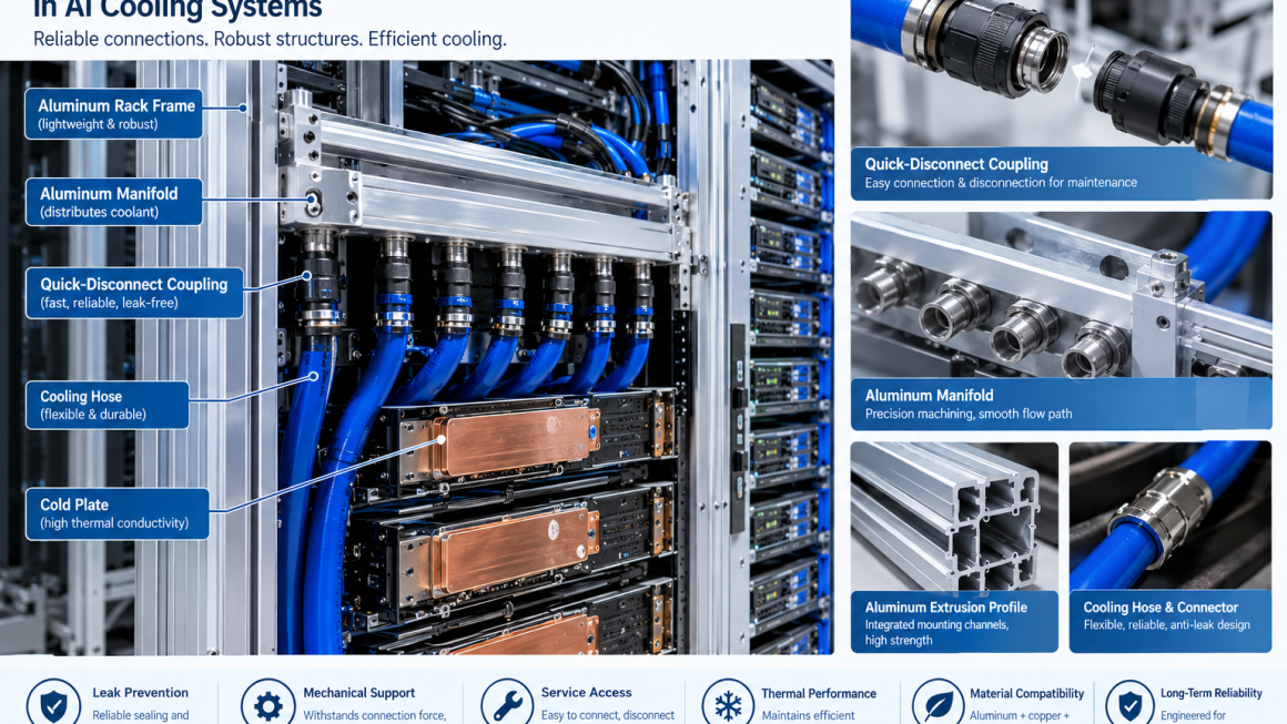
As AI servers move toward higher power densities, liquid cooling systems are becoming increasingly complex.
Modern AI cooling architectures may include:
- Cold plates
- Coolant distribution units
- Manifolds
- Flexible cooling hoses
- Quick-disconnect couplings
- Aluminum structural frames
- Server chassis
- Rack-level distribution components
Among these components, the quick disconnect coupling AI liquid cooling interface may appear relatively small compared with a server rack or cold plate.
However, the connector can have a significant influence on system reliability.
A quick-disconnect coupling is not simply a point where two hoses are joined.
It is simultaneously:
- A fluid interface
- A mechanical interface
- A service interface
- A sealing interface
- A potential load-transfer point
For aluminum AI infrastructure, this means the surrounding structure should be designed around the connector rather than treating it as an accessory added at the end of the project.
A reliable architecture considers:
QD Coupling → Hose → Manifold → Aluminum Support Structure → Rack
as one integrated mechanical and thermal system.
1. What Is a Quick-Disconnect Coupling in AI Liquid Cooling?
A quick-disconnect coupling, often called a QD, allows two sections of a cooling circuit to be connected and disconnected without permanently joining the fluid lines.
In AI liquid cooling systems, QDs may be used between:
- Server and rack manifold
- Cold plate and cooling loop
- Server module and distribution manifold
- Cooling hose and equipment interface
The exact coupling design depends on the cooling architecture.
Typical engineering requirements include:
- Reliable sealing
- Low leakage risk
- Appropriate flow capacity
- Controlled pressure drop
- Easy connection and disconnection
- Long service life
- Compatibility with the coolant
- Compatibility with surrounding materials
For service-intensive AI infrastructure, these requirements become especially important.
2. Why QD Interfaces Matter in High-Density AI Servers
AI servers are becoming more difficult to service because of:
- Higher GPU density
- More cooling connections
- Higher coolant flow requirements
- More complex cable routing
- Greater equipment weight
A conventional server may primarily require electrical and mechanical connections.
A liquid-cooled AI server can require both electrical and fluid connections.
This creates an additional service interface.
When a technician removes a server, the cooling connections must be handled safely and repeatedly.
Therefore, the QD interface needs to be considered during the original mechanical design.
3. A QD Is Also a Mechanical Interface
This is one of the most important principles in liquid cooling system design.
When a cooling hose is connected to a QD, the connector does not experience only fluid pressure.
It may also experience mechanical forces from:
- Hose weight
- Hose bending
- Hose routing
- Connector insertion
- Connector removal
- Thermal expansion
- Vibration
- Accidental movement
These forces can be transferred to the mounting structure.
If the QD is attached directly to a thin panel or poorly supported aluminum profile, the connector may introduce local stress.
Therefore:
The connector should be structurally supported, not simply mounted.
4. Connection Forces and Aluminum Structures
Aluminum is widely used in AI infrastructure because of its:
- Low density
- Good strength-to-weight characteristics
- Excellent extrusion capability
- Good machinability
- Corrosion resistance when properly designed and treated
However, aluminum structures still need to be designed for localized loads.
A QD connection can create concentrated loading at a relatively small mounting area.
Potential structural concerns include:
- Local deformation
- Fastener loosening
- Panel bending
- Profile rotation
- Joint fatigue
- Misalignment
This is especially important when multiple cooling hoses are connected to the same manifold or rack structure.
5. Supporting QD Cooling Interfaces
A well-designed QD cooling interface normally requires a defined mechanical support strategy.
Possible approaches include:
Direct Profile Mounting
The QD bracket attaches directly to an aluminum extrusion.
Advantages:
- Simple construction
- Modular layout
- Easy adjustment
Reinforced Mounting Plate
A thicker aluminum plate distributes the connector load.
Advantages:
- Better local stiffness
- Improved load distribution
- Suitable for concentrated connector loads
Dedicated Manifold Support
The manifold and QDs are supported by a dedicated aluminum structure.
Advantages:
- Better load management
- Easier service access
- Cleaner hose routing
The appropriate solution depends on the connector size, hose configuration, and number of connections.
6. Hose Forces Should Not Be Ignored
The cooling hose itself can generate mechanical loads.
For example, a hose may be forced into a small bend radius because of limited rack space.
This can generate a restoring force at the QD.
The resulting load can be transferred into:
Hose → QD → Bracket → Aluminum Structure
If the support structure is too flexible, the connector may move.
This can make assembly more difficult and may increase mechanical stress on the sealing interface.
Therefore, hose routing and structural design should be developed together.
7. Hose Bend Radius and Connector Position
A cooling hose should not be forced into an unnecessarily tight bend.
The minimum bend radius depends on the specific hose construction and manufacturer requirements.
Engineers should consider:
- Hose diameter
- Hose construction
- Operating pressure
- Temperature
- Installation geometry
- Repeated movement
The QD position should provide enough space for the hose to transition naturally.
A practical design sequence is:
QD Location
↓
Hose Exit Direction
↓
Required Bend Radius
↓
Manifold Position
↓
Aluminum Support Structure
This is more reliable than selecting the structure first and attempting to force the cooling hose into the remaining space.
8. Serviceability Is a Core QD Design Requirement
The major advantage of a quick-disconnect coupling is serviceability.
A liquid-cooled AI server may need to be:
- Removed
- Replaced
- Upgraded
- Inspected
- Repaired
The cooling interface should therefore remain accessible.
Engineers should provide sufficient clearance around:
- QD body
- Locking mechanism
- Hose
- Adjacent connectors
- Cable bundles
A connector that technically works but cannot be accessed comfortably during maintenance is not a good service interface.
9. Designing Aluminum Structures Around Maintenance Access
Aluminum extrusion systems can be particularly useful for serviceable liquid cooling infrastructure.
Extruded profiles can provide:
- Modular mounting channels
- Adjustable brackets
- Multiple fastening positions
- Reinforcement options
- Cable and hose management
This allows the QD location to be modified without redesigning the entire rack.
For example:
Aluminum Profile
→ adjustable QD bracket
→ cooling hose
→ server interface
This type of modular architecture can simplify future system revisions.
10. Leak Prevention at the QD Interface
Leak prevention is one of the most important considerations for any AI liquid cooling connector.
A QD interface typically relies on internal sealing components and controlled mechanical engagement.
Potential leakage risks can arise from:
- Damaged seals
- Incorrect connection
- Contamination
- Misalignment
- Excessive mechanical loading
- Hose movement
- Improper installation
The surrounding aluminum structure therefore has an indirect role in leak prevention.
If the structure allows excessive connector movement, the fluid interface may experience unnecessary mechanical stress.
11. Alignment Between QD and Aluminum Structure
Connector alignment is particularly important in dense AI server systems.
Misalignment can occur when:
- Brackets are too flexible
- Profiles deform under load
- Manufacturing tolerances accumulate
- Thermal expansion changes component position
A rigid but properly toleranced support structure can help maintain alignment.
However, the design should also allow the appropriate amount of movement where thermal expansion or installation tolerance requires it.
The goal is not simply:
Maximum rigidity
but rather:
Controlled movement + stable alignment
12. Fixed and Floating Mounting Strategies
Not every cooling interface should be rigidly fixed.
A system may use:
Fixed Mount
Used to establish a stable reference point.
Floating Mount
Allows controlled movement due to:
- Thermal expansion
- Installation tolerance
- Component movement
For aluminum structures, this can be particularly useful because aluminum has a relatively high coefficient of thermal expansion.
A properly designed mounting system can prevent unnecessary thermal stress from being transferred directly into the QD.
13. QD Couplings and Thermal Expansion
Liquid cooling systems operate across temperature ranges.
As the system heats and cools:
- Aluminum structures expand and contract.
- Copper components expand and contract.
- Hoses change shape.
- Manifold positions may shift slightly.
If the QD interface is rigidly constrained at multiple locations, thermal movement can generate additional loads.
Therefore, engineers should evaluate:
- Reference points
- Sliding interfaces
- Flexible hose sections
- Bracket stiffness
- Thermal expansion direction
The objective is to ensure that normal temperature changes do not become excessive connector loads.
14. QD Placement in AI Server Racks
Connector location affects both cooling performance and serviceability.
Possible locations include:
- Front of server
- Rear of server
- Rack-side manifold
- Top distribution area
- Bottom distribution area
Each arrangement has different consequences for:
- Hose length
- Bend radius
- Service access
- Airflow
- Cable routing
- Structural loading
There is no universally correct QD location.
The correct location depends on the complete rack architecture.
15. Integrating QDs With Aluminum Manifolds
An aluminum manifold can distribute coolant to multiple AI servers.
The manifold may contain several QD interfaces.
This creates a concentrated group of mechanical loads.
The design should consider:
- Manifold wall thickness
- Mounting locations
- Connector spacing
- Local reinforcement
- Pressure loads
- Hose routing
The manifold itself should not be treated as an isolated fluid component.
It is also part of the rack’s mechanical infrastructure.
16. Pressure Drop and Connector Selection
A QD must provide sufficient flow without creating excessive pressure drop.
Important parameters include:
- Nominal flow rate
- Internal passage size
- Connector geometry
- Number of QDs in the loop
- Coolant viscosity
In high-density AI cooling systems, multiple connectors may exist in series.
Therefore:
QD pressure drop × number of interfaces
can become an important part of the overall hydraulic design.
Connector selection should therefore be based on the actual cooling loop rather than connector size alone.
17. Material Compatibility at the QD Interface
AI cooling systems often combine:
- Aluminum
- Copper
- Stainless steel
- Brass
- Polymer materials
This makes material compatibility important.
Engineers should evaluate:
- Coolant chemistry
- Galvanic corrosion
- Seal compatibility
- Temperature range
- Surface treatment
For aluminum-containing cooling systems, coolant compatibility should be verified rather than assumed.
This is especially important when aluminum components are directly exposed to the coolant.
18. Aluminum Surface Treatment Around Cooling Interfaces
Surface treatment may be useful for aluminum structural components surrounding the QD.
Possible options include:
- Anodizing
- Conversion coatings
- Protective coatings
However, the treatment should match the function of the surface.
For example:
Structural Surface
Corrosion and wear protection may be prioritized.
Grounding Surface
Electrical continuity may be required.
Sealing Surface
Surface geometry and finish may be more important than decorative appearance.
Coolant-Contact Surface
Chemical compatibility becomes a primary consideration.
A single surface treatment should not automatically be applied to every aluminum component in a liquid cooling system.
19. Fasteners and QD Brackets
Fasteners are small components but can have a major influence on reliability.
A QD bracket may experience repeated mechanical loading.
Engineers should consider:
- Fastener material
- Thread engagement
- Joint stiffness
- Locking method
- Torque control
- Galvanic compatibility
For aluminum structures, thread design is particularly important where components will be repeatedly assembled and serviced.
In some applications, threaded inserts or dedicated mounting hardware may provide better long-term serviceability.
20. Vibration and Repeated Service
AI infrastructure can experience vibration during:
- Equipment transportation
- Rack installation
- Fan operation
- Pump operation
- Maintenance
Repeated connection and disconnection also introduces mechanical cycling.
The QD support structure should therefore be designed for the expected service environment.
Potential validation methods include:
- Vibration testing
- Repeated connection testing
- Pressure testing
- Leak testing
- Thermal cycling
21. Designing for Leak Detection and Maintenance
Liquid cooling infrastructure should also consider what happens if a leak occurs.
The mechanical structure can support:
- Drainage paths
- Access panels
- Inspection areas
- Leak detection devices
- Replaceable hose sections
For example, an aluminum rack structure can provide defined service zones around cooling interfaces.
This can make inspection easier without requiring major disassembly.
22. Manufacturing Aluminum Structures for QD Integration
A well-designed QD support structure must also be manufacturable.
Common processes include:
- Aluminum extrusion
- CNC machining
- Drilling and tapping
- Cutting
- Deburring
- Anodizing
- Assembly
Extrusion is particularly useful for modular structures because mounting channels and reinforcement features can be integrated directly into the profile.
CNC machining can then create:
- Connector mounting holes
- Manifold interfaces
- Precision locating features
- Fastener positions
This combination provides flexibility for both prototype and production programs.
23. Prototype-to-Production Considerations
QD interfaces often change during development.
Early prototypes may reveal:
- Hose interference
- Poor connector access
- Excessive bracket movement
- Difficult maintenance
- Unexpected installation loads
This makes rapid prototyping valuable.
A practical development sequence is:
Initial Layout
→ Prototype Aluminum Structure
→ QD + Hose Assembly
→ Mechanical Validation
→ Cooling Loop Testing
→ Design Optimization
→ Production
This approach can identify interface problems before production tooling or large-volume manufacturing.
24. A Practical Design Workflow
When designing an aluminum structure around an AI liquid cooling connector, engineers can follow this sequence.
Step 1: Define the Cooling Architecture
Identify:
- Server
- Cold plate
- Manifold
- Hose
- QD
- CDU
Step 2: Define QD Requirements
Determine:
- Flow
- Pressure
- Temperature
- Connection method
- Service frequency
Step 3: Map Mechanical Loads
Consider:
- Hose forces
- Connection forces
- Weight
- Vibration
- Thermal expansion
Step 4: Design the Aluminum Support
Define:
- Profile geometry
- Bracket thickness
- Reinforcement
- Fasteners
Step 5: Check Service Access
Verify:
- Hand clearance
- Connector access
- Hose movement
- Server removal path
Step 6: Validate
Perform:
- Structural testing
- Pressure testing
- Leak testing
- Thermal cycling
- Service-cycle testing
25. Common QD Design Mistakes
Mistake 1: Treating the QD as a Fluid-Only Component
The connector also transfers mechanical loads.
Mistake 2: Ignoring Hose Forces
A hose under bending or tension can apply significant loads to the connector.
Mistake 3: Designing Without Maintenance Access
A connector that cannot be reached easily creates service problems.
Mistake 4: Over-Constraining the Cooling Loop
Rigid mounting can transfer thermal expansion forces into the connector.
Mistake 5: Ignoring Material Compatibility
Aluminum, copper, brass, stainless steel, and coolant chemistry must be evaluated together.
Mistake 6: Using a Flexible Structure for a Precision Interface
Some flexibility is useful, but excessive movement can affect alignment and serviceability.
Mistake 7: Designing the Rack First and the Cooling Interface Later
The QD, hose, manifold, and supporting structure should be developed as an integrated assembly.
26. Why Aluminum Extrusion Works Well Around QD Interfaces
Aluminum extrusion provides several advantages for liquid cooling infrastructure.
It allows engineers to create profiles with:
- Internal cavities
- Reinforcing ribs
- Mounting channels
- Fastener tracks
- Cable-routing features
- Hose-support features
This makes it possible to build a structural platform around the cooling interface.
Instead of designing a separate bracket for every component, an extrusion-based architecture can provide a common mechanical platform.
This is particularly useful for modular AI racks where cooling configurations may evolve.
27. Aluminum + QD + Liquid Cooling: An Integrated Design Philosophy
The most reliable approach is to consider the entire interface as one system.
Fluid Function
QD → Hose → Manifold → Cold Plate
Mechanical Function
QD → Bracket → Aluminum Profile → Rack
Thermal Function
Cold Plate → Coolant → Heat Rejection System
Service Function
Server → QD → Hose → Disconnect → Remove
All four functions must work together.
A change in one area can affect the others.
For example:
Moving a QD may improve service access but increase hose bending.
Increasing bracket stiffness may improve alignment but restrict thermal movement.
Changing connector size may improve flow but require a larger mounting structure.
This is why QD interface design should be considered at the system level.
28. The Future of AI Liquid Cooling Interfaces
As AI server power density continues to increase, cooling infrastructure will become more modular.
Future AI cooling systems are likely to place greater emphasis on:
- Higher-flow interfaces
- Lower pressure drop
- Improved leak prevention
- Easier maintenance
- Modular rack architecture
- Better monitoring
- More integrated mechanical design
The QD will increasingly become a standardized service interface between the server and the cooling infrastructure.
This creates new opportunities for aluminum structural design around:
- Connector brackets
- Manifolds
- Rack-side interfaces
- Hose management
- Modular cooling frames
QD Interfaces Should Be Designed as Part of the Aluminum Structure
A quick disconnect coupling AI liquid cooling system is more than a connector between two hoses.
It is an important interface between:
Fluid → Mechanical Structure → Thermal System → Maintenance Process
For AI infrastructure, the surrounding aluminum structure should account for:
- Connection forces
- Hose bending forces
- Connector alignment
- Thermal expansion
- Vibration
- Fastener loading
- Leak prevention
- Service access
- Material compatibility
A well-designed AI server liquid cooling connector should therefore be integrated with the rack and cooling architecture from the beginning.
The design chain is simple:
QD Selection
→ Hose Routing
→ Mechanical Support
→ Aluminum Structural Integration
→ Thermal & Fluid Validation
→ Serviceability Validation
→ Production
When these elements are designed together, aluminum structures can provide a lightweight, modular platform for reliable liquid-cooled AI infrastructure.
The goal is not simply to connect a cooling hose.
The goal is to create a reliable, serviceable, mechanically stable cooling interface for high-density AI systems.