



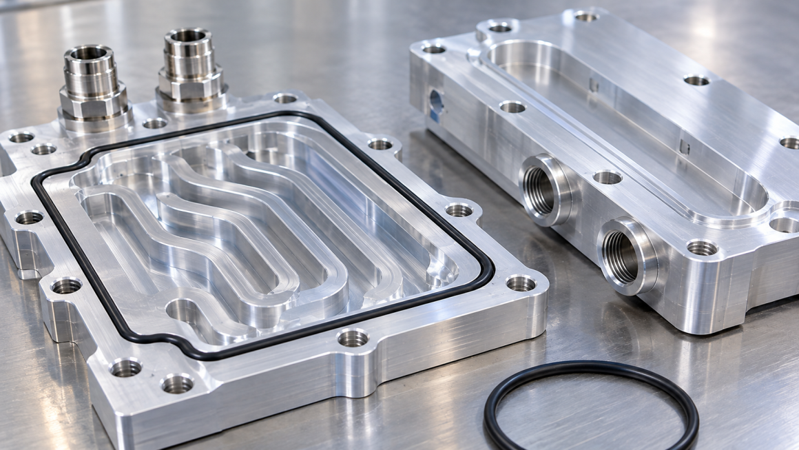
Aluminum cold plates and coolant manifolds are important components in liquid-cooled AI servers and high-density data center infrastructure. They provide coolant distribution paths and thermal interfaces for high-power GPUs, CPUs, and other heat-generating components.
As liquid cooling systems become more compact and operate under increasingly demanding conditions, the reliability of sealing interfaces becomes a critical engineering consideration.
A cold plate may have precisely machined internal channels and excellent thermal characteristics, but these advantages can be undermined by leakage at the cover plate, manifold connection, or external fluid interface.
For aluminum cooling hardware, reliable sealing depends on several factors working together:
- O-ring material and cross-sectional dimensions
- O-ring groove geometry
- Sealing surface roughness
- Mating surface flatness
- O-ring compression and gland design
- Fastener arrangement and tightening sequence
- Coolant and material compatibility
- Operating pressure and temperature conditions
These factors should be considered during the mechanical design stage rather than addressed only after a leakage problem appears.
This article examines the key engineering considerations for aluminum cold plate sealing design, with a focus on O-ring groove design, manifold sealing surfaces, dimensional control, assembly procedures, and validation under actual operating conditions.
1. Why Sealing Design Matters in Aluminum Cooling Components
In a liquid-cooled AI server, coolant may pass through multiple aluminum components, including:
- GPU and CPU cold plates
- Coolant distribution manifolds
- Liquid cooling distribution blocks
- Machined aluminum channels
- Connection plates and adapters
- Rack-level coolant distribution hardware
Each connection introduces one or more potential leakage interfaces.
Depending on the component architecture, sealing may be achieved through:
- O-rings installed in machined grooves
- Flat gaskets between mating surfaces
- Threaded connections with suitable sealing arrangements
- Specialized fittings and connector seals
- Permanently joined structures, such as qualified brazed or welded assemblies
O-rings are widely used because they provide an effective and compact sealing solution when correctly designed and installed.
However, an O-ring does not guarantee a leak-free connection by itself.
Its performance depends on the geometry of the groove, the condition of the mating surfaces, the amount of compression, the material properties, and the operating environment.
A sealing interface must therefore be treated as a complete mechanical system.
2. O-Ring Groove Design: Creating a Reliable Sealing Interface
The O-ring groove is one of the most important features in an aluminum cold plate or manifold.
Its purpose is to position the O-ring, control its deformation during assembly, and maintain the required contact pressure against the mating surfaces.
A groove that is too shallow, too deep, too narrow, or poorly machined may result in inadequate sealing or excessive deformation.
Groove depth
Groove depth determines how much the O-ring is compressed when the mating components are assembled.
If the groove is too deep, the O-ring may receive insufficient compression.
If the groove is too shallow, excessive compression may occur, potentially increasing assembly force and accelerating seal degradation.
The correct groove depth depends on the O-ring cross-section, sealing arrangement, material, and application requirements.
Groove width
Groove width provides space for the O-ring to deform during assembly.
The groove must accommodate the O-ring without excessive restriction while also preventing unwanted movement or extrusion.
Insufficient groove volume may cause excessive deformation, particularly when the O-ring expands due to temperature or fluid exposure.
Groove geometry
The groove should be manufactured with controlled dimensions and suitable edge conditions.
Important considerations include:
- Groove width and depth
- Corner radii
- Surface finish
- Machining burrs
- Edge sharpness
- Position relative to the fluid passage
- Distance from nearby fasteners and structural features
Sharp edges and machining burrs can damage an O-ring during installation.
The groove should also provide a consistent sealing path without unintended interruptions or surface defects.
Static and dynamic sealing
Most cold plate cover interfaces use static O-ring seals, where the mating components remain fixed relative to each other after assembly.
However, certain connector or service interfaces may experience repeated movement.
Dynamic sealing applications require additional consideration of friction, wear, lubrication, movement speed, and material behavior.
The groove design should therefore reflect whether the seal is intended for static or dynamic service.
3. O-Ring Compression: Balancing Sealing Performance and Material Deformation
O-ring compression, commonly referred to as squeeze, is a fundamental parameter in sealing design.
It describes the deformation of the O-ring cross-section when the sealing interface is assembled.
For a simple axial face seal, squeeze can be expressed as:
[
S=\frac{d-h}{d}\times100%
]
Where:
- (S) = percentage compression
- (d) = original O-ring cross-sectional diameter
- (h) = installed gland height or effective gap
This is a simplified geometric relationship. Actual gland design must also consider tolerances, O-ring dimensions, material behavior, thermal effects, and the applicable sealing standard.
Insufficient compression
If the O-ring is compressed too little, it may not generate sufficient contact pressure to maintain a reliable seal.
Potential problems include:
- Leakage during pressure changes
- Sensitivity to surface irregularities
- Reduced sealing reliability under temperature variation
- Loss of sealing contact due to dimensional tolerances
Excessive compression
Excessive compression may also create problems.
These can include:
- Increased assembly force
- Accelerated compression set
- Material damage during installation
- Reduced allowance for thermal expansion
- Increased risk of groove overfilling
The goal is not to maximize compression. It is to achieve an appropriate compression range for the selected O-ring material and sealing configuration.
Tolerance stack-up
A reliable design should consider the combined dimensional tolerances of:
- O-ring cross-section
- Groove depth
- Mating surface position
- Cover plate thickness
- Fastener and structural deformation
The actual compression may vary across the component if the mating surfaces are not sufficiently flat or the cover plate deforms during tightening.
This is why compression should be evaluated using the complete tolerance stack rather than nominal CAD dimensions alone.
4. Surface Roughness: Why Machined Sealing Surfaces Matter
Surface finish directly affects the contact conditions between the O-ring and its mating surface.
Even when an O-ring has the correct dimensions and compression, excessive surface roughness or machining defects may create leakage paths.
For aluminum cold plates and manifolds, sealing surfaces are commonly produced through CNC machining.
The machining process should provide a consistent surface suitable for the selected sealing method.
Surface roughness considerations
Engineers may evaluate surface roughness using parameters such as:
- Ra: arithmetic average roughness
- Rz: average maximum profile height, depending on the measurement standard and definition used
Ra is useful for general surface characterization, but it does not fully describe the surface profile.
Two surfaces with similar Ra values may have different peak shapes, scratches, machining marks, or isolated defects.
For O-ring sealing surfaces, the direction and character of machining marks can also matter.
Deep scratches or continuous tool marks crossing the sealing path may create potential leakage channels.
CNC machining considerations
To improve sealing surface consistency:
- Use suitable finishing operations.
- Control tool condition and machining parameters.
- Avoid burrs and sharp edges near the sealing path.
- Inspect for scratches and localized defects.
- Maintain consistent machining references.
- Protect finished sealing surfaces during handling and assembly.
Surface roughness requirements should be established according to the O-ring material, sealing type, pressure conditions, and relevant engineering guidance.
A single roughness value should not be applied indiscriminately to every sealing interface.
5. Flatness: Maintaining Uniform Contact Across the Sealing Interface
Flatness is another critical parameter for aluminum cold plate and manifold sealing.
When two mating surfaces are assembled, they must maintain an appropriate geometric relationship to ensure that the O-ring receives sufficiently uniform compression.
If the sealing surface is warped or locally deformed, the compression may vary across the interface.
Some areas may receive excessive compression while others receive insufficient compression.
Factors affecting flatness
Several manufacturing and assembly factors may influence flatness:
- CNC machining strategy
- Residual stress in the aluminum material
- Component wall thickness
- Material removal distribution
- Clamping during machining
- Heat generated during manufacturing
- Fastener tightening forces
- Pressure-induced deformation
Large or thin-walled aluminum cold plates may be particularly sensitive to machining and assembly deformation.
Design and manufacturing considerations
Engineers should consider:
Material selection and preparation
Material condition and residual stress may influence dimensional stability during machining.
Machining sequence
Roughing and finishing operations should be planned to reduce distortion.
Fixture design
Machining fixtures should provide adequate support without introducing excessive deformation.
Inspection method
Flatness should be measured using an appropriate method and reference system.
Assembly behavior
The component should be evaluated under its intended fastening arrangement, because a surface that is flat before assembly may deform during tightening.
For larger sealing interfaces, local flatness and overall component deformation may both need to be considered.
6. Fastener Arrangement and Tightening Sequence
Even a well-designed O-ring groove can fail to provide consistent sealing if the mating components are assembled incorrectly.
Fasteners apply clamping forces that compress the O-ring and hold the sealing surfaces together.
If the clamping force is distributed unevenly, local deformation may occur.
This can result in non-uniform O-ring compression and potential leakage.
Fastener layout
The number and position of fasteners influence the stiffness and deformation behavior of the assembly.
Important considerations include:
- Fastener spacing
- Distance from the sealing path
- Cover plate thickness
- Local structural stiffness
- Thread engagement
- Fastener material
- Required preload
- Operating pressure loads
For larger aluminum manifolds, a limited number of widely spaced fasteners may allow the cover plate to deform between fastening points.
Additional fastening locations or a stiffer cover structure may help improve clamping uniformity, depending on the design.
Tightening sequence
A controlled tightening sequence helps distribute clamping forces more evenly.
For components with multiple fasteners, a cross-pattern or staged tightening sequence may be appropriate.
A typical procedure may involve:
- Positioning the O-ring correctly in its groove.
- Aligning the mating components.
- Installing all fasteners without fully tightening them.
- Applying an initial low-level tightening stage.
- Tightening progressively in the specified sequence.
- Applying the final specified torque or preload.
- Inspecting the assembled interface.
The exact sequence and torque values must be established for the specific assembly.
Torque alone does not precisely determine fastener preload because friction, lubrication, thread condition, and fastener geometry all influence the relationship.
For critical applications, the fastening method should be defined and verified through an appropriate engineering procedure.
7. O-Ring Material Compatibility with Coolants and Operating Temperatures
Selecting an O-ring based only on its nominal size is insufficient.
The material must be compatible with the coolant, operating temperature, pressure conditions, and expected service life.
Common elastomer families used in industrial sealing applications include:
- EPDM
- FKM
- NBR
- Silicone
- Other application-specific elastomer compounds
These materials have different chemical, thermal, mechanical, and compression-set characteristics.
Coolant compatibility
Liquid cooling systems may use different coolant formulations, including water-based mixtures and specialized industrial fluids.
The O-ring material must be evaluated against the actual coolant formulation rather than selected based on a general material category.
Important factors include:
- Base fluid composition
- Glycol concentration, if applicable
- Additives and corrosion inhibitors
- Operating temperature
- Exposure duration
- Fluid contamination
- Cleaning and flushing chemicals
A material that performs well in one water-glycol formulation may not have the same compatibility with another fluid.
Temperature-related behavior
Temperature affects elastomer properties.
Depending on the material and operating conditions, changes may occur in:
- Elasticity
- Hardness
- Compression set
- Chemical resistance
- Dimensional stability
- Long-term sealing behavior
The selected material should be qualified for the complete operating temperature range, including expected startup, shutdown, and transient conditions.
Compatibility with aluminum
O-ring material selection is only one part of material compatibility.
The complete cooling assembly may include aluminum, copper, stainless steel, brass, polymers, coatings, and elastomers.
Coolant chemistry and material interactions should be evaluated at system level, particularly where different metals are in contact.
Corrosion inhibitors and fluid formulation may influence long-term compatibility.
8. Pressure and Temperature: Understanding Real Operating Conditions
A sealing design that passes an initial room-temperature leakage test may still experience problems under actual operating conditions.
Liquid cooling systems operate under varying temperatures and pressure conditions.
Potential changes include:
- Pressure fluctuations during pump operation
- Temperature changes during server load transitions
- Thermal expansion of aluminum components
- Changes in elastomer properties
- Mechanical deformation of cover plates
- Repeated startup and shutdown cycles
These factors may influence the contact pressure and dimensional relationship at the sealing interface.
Pressure considerations
The sealing design should account for the specified operating pressure and any relevant pressure transients.
The pressure boundary must also consider the structural integrity of the cold plate, cover plate, fasteners, and connecting components.
An O-ring may be suitable for a particular pressure range only when the gland geometry, material, extrusion gap, and assembly conditions are also appropriate.
Temperature considerations
Aluminum and elastomers respond differently to temperature changes.
Aluminum expands and contracts with temperature, while elastomers exhibit temperature-dependent changes in elasticity and dimensions.
These differences can influence the sealing interface.
Engineers should evaluate whether thermal cycling could cause:
- Changes in O-ring compression
- Relative movement between mating components
- Changes in fastener preload
- Local distortion of the sealing surface
- Long-term degradation of the elastomer
The actual effect depends on component geometry, material selection, temperature range, and assembly design.
9. O-Ring Extrusion and Pressure-Related Sealing Risks
In pressurized systems, an O-ring may be forced into the clearance between mating components.
This phenomenon is commonly referred to as extrusion.
It can damage the seal and reduce long-term reliability.
The risk depends on factors including:
- Operating pressure
- Pressure peaks
- Elastomer hardness
- Material properties
- Clearance gap
- Temperature
- Groove geometry
The clearance between the mating components should therefore be considered during gland design.
For higher-pressure applications, an appropriate elastomer compound, tighter dimensional control, or backup-ring arrangement may be required.
Backup rings are not universally necessary. Their use depends on the actual pressure, clearance, material, and sealing configuration.
The sealing design should follow the applicable engineering standards and the selected O-ring manufacturer’s recommendations.
10. Manufacturing Quality Control for Aluminum Sealing Interfaces
Reliable sealing depends on manufacturing consistency.
Even a design with suitable nominal dimensions can experience leakage if critical features are not controlled during production.
For aluminum cold plates and manifolds, important quality-control items include:
| Inspection item | Main purpose |
|---|---|
| Groove depth and width | Verify O-ring gland geometry |
| Groove position | Confirm sealing-path alignment |
| Surface roughness | Check sealing surface condition |
| Flatness | Verify mating surface geometry |
| Burr and scratch inspection | Identify potential leakage paths or seal damage |
| Port and channel inspection | Confirm internal flow-path quality |
| Thread inspection | Verify fastener interface quality |
| Material verification | Confirm aluminum and elastomer specifications |
| Assembly inspection | Check O-ring positioning and fastening |
| Pressure and leak testing | Verify assembled fluid integrity |
Inspection methods should be selected according to the component’s geometry and required tolerances.
For example, a coordinate measuring machine may be useful for checking critical dimensions and flatness, while surface roughness instruments can assess the machined sealing interface.
Internal passages may require additional inspection and cleaning procedures.
11. Pressure Testing and Leak Validation
Pressure and leakage testing are essential parts of validating aluminum cold plates and manifolds.
However, testing should be designed around the actual application rather than treated as a simple pass-or-fail operation.
A practical validation program may include:
Dimensional inspection before assembly
Verify groove dimensions, surface finish, flatness, and critical mating features.
Assembly verification
Confirm the correct O-ring material and size, groove positioning, lubrication requirements where applicable, and fastening procedure.
Initial leak testing
Perform an appropriate leakage test after assembly using a qualified test procedure.
Pressure testing
Evaluate the component or assembly under the specified test pressure and duration.
The test pressure should be defined by the engineering design and applicable standards. It should not be selected arbitrarily or assumed to be a universal multiple of operating pressure.
Temperature and pressure cycling
Where required, evaluate the assembly under representative temperature and pressure changes.
Post-test inspection
Inspect the O-ring, sealing surfaces, fasteners, and component structure for damage or deformation.
Repeated assembly evaluation
For serviceable designs, repeated disassembly and reassembly may need to be evaluated to understand the effect on sealing reliability.
Testing methods should distinguish between hydrostatic pressure testing, pneumatic testing, and leak-rate measurement. These methods have different safety requirements and detect different types of leakage.
The final validation should reflect the intended operating environment and system-level requirements.
12. Common Sealing Design Mistakes
Several recurring design and manufacturing problems can reduce the reliability of aluminum cooling components.
1. Selecting an O-ring without evaluating coolant compatibility
A seal may have suitable dimensions but may degrade when exposed to the actual coolant formulation.
2. Designing the groove only from nominal O-ring dimensions
Tolerance variation and gland volume are overlooked, leading to insufficient or excessive compression.
3. Ignoring surface defects
Scratches, burrs, or unsuitable machining marks may create leakage paths or damage the elastomer.
4. Assuming nominal flatness guarantees assembled flatness
Fastener loads and pressure-induced deformation can change the actual sealing interface.
5. Tightening fasteners inconsistently
Uneven clamping may create local variations in O-ring compression.
6. Ignoring extrusion clearance
The O-ring may be damaged under pressure if the clearance and material are not suitable.
7. Relying only on room-temperature leak testing
The assembly may behave differently under operating temperature and pressure cycles.
8. Reusing seals without an approved procedure
O-rings may suffer compression set, surface damage, or contamination during disassembly.
A reliable design requires coordinated control of materials, geometry, machining, assembly, and testing.
13. From Prototype to Production: A Practical Sealing Design Workflow
For manufacturers developing custom aluminum cold plates and coolant manifolds, sealing should be incorporated into the initial mechanical design.
A structured workflow can help reduce redesign and production risks.
Step 1: Define operating conditions
Establish the coolant type, operating temperature range, pressure range, pressure transients, expected service life, and maintenance requirements.
Step 2: Select the sealing architecture
Determine whether the application requires an O-ring, flat gasket, threaded seal, or another suitable sealing method.
Step 3: Select the O-ring material and dimensions
Evaluate elastomer compatibility, cross-section, hardness, temperature limits, and pressure requirements.
Step 4: Design the groove
Establish groove depth, width, corner radii, gland volume, and tolerance requirements using the applicable design guidance.
Step 5: Define sealing surface requirements
Specify flatness, roughness, machining quality, and inspection methods.
Step 6: Evaluate structural deformation
Review cover plate stiffness, fastener layout, local stress, and possible deformation under assembly and operating pressure.
Step 7: Establish the assembly procedure
Define O-ring installation, lubrication where applicable, alignment, tightening sequence, and fastener requirements.
Step 8: Manufacture and inspect prototypes
Produce representative aluminum components and verify all critical sealing features.
Step 9: Conduct pressure and temperature validation
Evaluate leakage and structural integrity under representative operating conditions.
Step 10: Standardize production controls
Document material specifications, machining tolerances, assembly procedures, and inspection requirements for repeatable manufacturing.
This process connects sealing design with practical production engineering.
Sealing aluminum cold plates and manifolds requires more than selecting an O-ring with the correct dimensions.
O-ring groove geometry, compression, surface roughness, flatness, fastener arrangement, material compatibility, and operating conditions all influence sealing reliability.
For liquid-cooled AI infrastructure, even a small leakage issue can affect equipment availability and maintenance operations. Sealing performance should therefore be treated as a critical design and validation requirement.
Aluminum extrusion and CNC machining provide flexible manufacturing options for cold plates, manifolds, and associated connection structures. However, precision manufacturing must be combined with appropriate elastomer selection, dimensional inspection, controlled assembly, and pressure and temperature testing.
Ultimately, a reliable sealing interface is not defined by its CAD geometry alone. It must perform consistently in the actual pressure, temperature, coolant, and service conditions for which the cooling system is designed.