
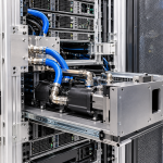
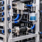
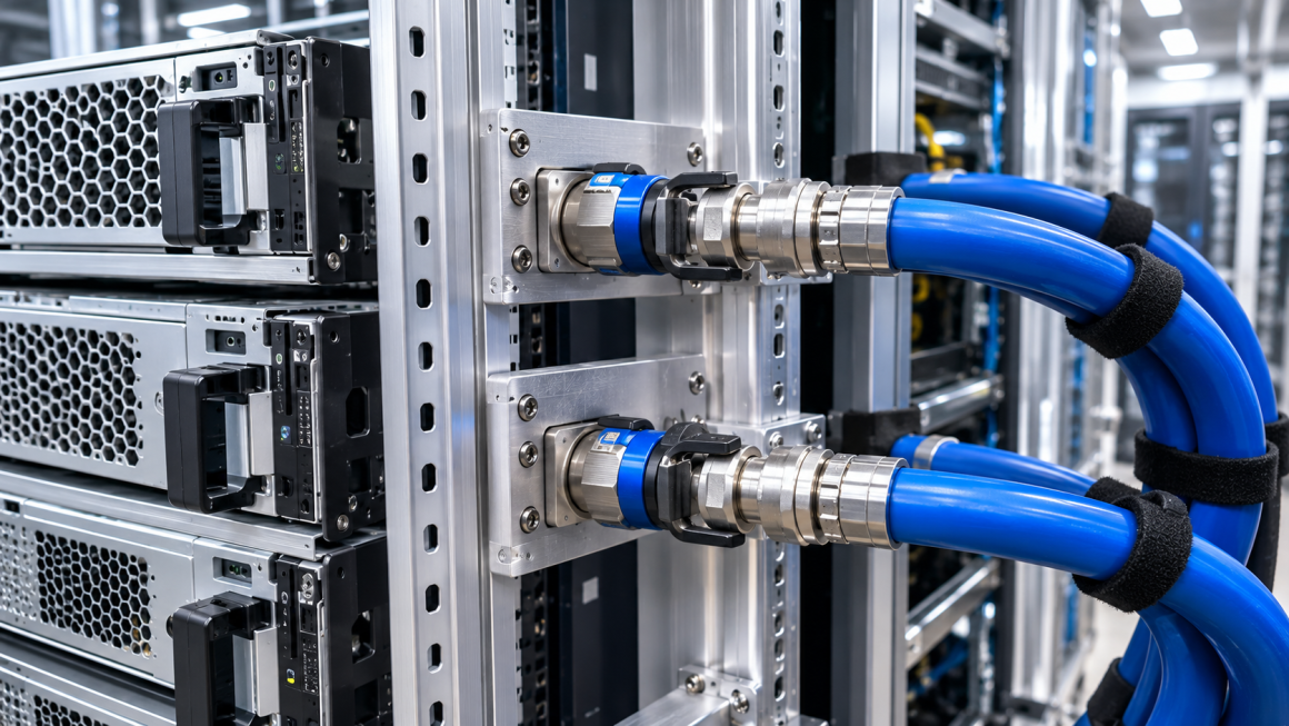
As AI servers become more powerful, liquid cooling is increasingly used to manage the thermal loads generated by high-density GPU systems. Quick-disconnect (QD) connectors play an important role in these systems by allowing coolant lines to be connected and disconnected during installation, maintenance, and component replacement.
However, integrating QD connectors into an AI rack is not simply a matter of selecting a compatible connector and attaching it to a hose. Their location, orientation, mounting structure, operating clearance, and mechanical support all influence serviceability and long-term reliability.
Aluminum rack structures can provide a lightweight and configurable platform for QD integration. But the mounting design must account for connector insertion and removal forces, hose movement, vibration, and maintenance access.
This article examines the key engineering considerations when integrating quick-disconnect connectors into aluminum liquid-cooled AI racks.
1. Why QD Integration Matters in AI Liquid Cooling Racks
In a liquid-cooled AI rack, QD connectors may be installed at several interfaces, including:
- Server-level coolant supply and return connections
- Rack-level coolant distribution manifolds
- Flexible hose connections between equipment modules
- Cooling distribution units and rack interfaces
- Service connections for replaceable cooling components
Their primary function is to enable controlled connection and disconnection without requiring extensive disassembly of the cooling system.
For maintenance teams, this can reduce the time required to replace a server, cooling module, or individual component. However, the practical benefit depends on whether technicians can safely access and operate the connectors.
A connector that is technically compatible but difficult to reach, improperly supported, or blocked by neighboring hardware can become a maintenance bottleneck.
QD integration should therefore be considered during the early rack structural design stage rather than added after the aluminum frame and piping layout have been finalized.
2. Installation Space: Allowing Enough Room Around Each Connector
One of the first design considerations is the physical space required for QD installation and operation.
The connector body itself represents only part of the required envelope. Engineers must also consider the space needed for:
- The mating and unmating movement
- The operator’s hand or service tool
- Connector locking and release mechanisms
- Hose bending and routing
- Adjacent connectors and structural members
- Inspection and replacement activities
A connector may fit within a narrow space when installed, yet remain difficult to disconnect because there is insufficient clearance for the operator to grip the release sleeve or move the connector through its required travel.
This is particularly important in high-density GPU racks, where server rails, power cables, data cables, and coolant lines compete for limited space.
Design considerations
The QD installation envelope should be evaluated using the manufacturer’s dimensional drawings and operating instructions.
The design should distinguish between:
- Installed envelope: The space occupied by the connected QD assembly.
- Operating envelope: The clearance required to connect and disconnect it.
- Maintenance envelope: The additional access space needed for hands, tools, inspection, and component replacement.
Aluminum mounting brackets and adjustable rails can help position connectors at accessible locations while maintaining a compact rack layout.
3. Connector Orientation: Designing for Practical Service Access
QD connector orientation directly affects how easily technicians can operate the cooling system.
Common installation orientations include:
- Horizontal connections facing the front or rear of the rack
- Vertical connections along a rack-side distribution structure
- Angled connections designed to accommodate hose routing
- Side-mounted connections integrated into aluminum brackets or manifolds
There is no universally optimal orientation. The appropriate choice depends on the connector design, hose direction, available clearance, and maintenance procedure.
For example, a front-facing connector may simplify server replacement when the rack is serviced from the front. However, it may interfere with server extraction or other front-access components if its position is not carefully coordinated.
Similarly, vertically arranged QDs can improve the use of rack-side space, but technicians must still be able to reach the release mechanism and support the hose during disconnection.
Avoiding orientation-related problems
Engineers should verify:
- Whether the release mechanism can be operated in the selected orientation
- Whether the connector can be disconnected without twisting the hose excessively
- Whether neighboring connectors interfere with access
- Whether the hose can maintain its required bend radius
- Whether coolant supply and return connections are clearly identified
A well-designed connector layout should make the correct service procedure intuitive and repeatable.
4. Insertion and Removal Forces: Why Structural Support Matters
QD connectors require a certain amount of force to connect and disconnect. The actual force depends on connector type, size, pressure conditions, seal design, locking mechanism, and manufacturer specifications.
During operation, technicians apply mechanical force to the connector assembly. If the connector is mounted directly to a flexible panel or an inadequately supported bracket, this force may cause unwanted movement.
Potential consequences include:
- Bracket deformation
- Movement of the manifold or mounting panel
- Unnecessary loading on connected pipes
- Misalignment during reconnection
- Increased difficulty during maintenance
The rack structure should provide a stable reaction point for the expected operating forces.
Mounting design principles
For aluminum rack structures, several approaches can be considered:
Reinforced mounting brackets
Use appropriately sized aluminum brackets to distribute connector operating forces into the main frame rather than concentrating them on a thin panel.
Short and rigid load paths
Keep the mechanical connection between the QD mounting point and the main structural member as direct as practical.
Multiple-point fastening
Where appropriate, use multiple fastening points to reduce bracket rotation and local deformation.
Dedicated connector support
For larger or heavier connector assemblies, consider a dedicated support plate or mounting rail rather than relying on the hose or manifold connection to hold the connector in position.
The objective is not simply to make the bracket strong. It is to ensure that the connector remains sufficiently stable and aligned during repeated service operations.
5. Mounting Rigidity and Aluminum Structural Design
Aluminum is widely used in AI rack structures because of its low density, manufacturing flexibility, and suitability for extrusion and CNC machining.
These characteristics make it useful for designing modular QD mounting systems.
However, aluminum components still require appropriate structural sizing. A lightweight mounting bracket may be convenient for assembly, but excessive flexibility can compromise connector operation.
Important design parameters include:
- Bracket thickness and unsupported length
- Extrusion profile geometry
- Fastener spacing and engagement
- Local bearing stress around mounting holes
- Deflection under connector operating forces
- Vibration and fatigue under operating conditions
For modular rack designs, T-slot aluminum profiles or custom extrusions can provide adjustable mounting positions. CNC-machined plates and brackets can then be used to create precise interfaces for specific QD connector models.
A hybrid approach can be particularly useful: extruded profiles provide the main structural framework, while machined aluminum components provide the connector-specific mounting features.
The final design should be verified against actual connector operating forces and the expected service cycle.
6. Hose Routing and Mechanical Loads on QD Connectors
A common integration mistake is allowing the hose to place unnecessary mechanical loads on the connector.
Liquid-cooling hoses may experience forces from:
- Their own weight
- Internal pressure and pressure fluctuations
- Bending and torsion
- Thermal expansion and contraction
- Movement during server installation or removal
- Vibration during equipment operation
If these loads are transferred directly to the QD connector, they may contribute to misalignment, wear, seal damage, or mechanical stress at the connection.
Supporting the hose independently
Where practical, hose supports should be positioned to reduce unnecessary loads on the connector.
For example:
- Use dedicated clamps or brackets to support heavier hose sections.
- Avoid sharp bends immediately adjacent to the connector.
- Maintain the hose manufacturer’s minimum bend radius.
- Provide sufficient flexibility for server insertion and removal.
- Prevent hoses from rubbing against sharp aluminum edges.
- Avoid routing arrangements that require the connector to carry hose weight.
The connector should primarily perform its intended connection function, rather than acting as a structural support for the entire hose assembly.
Engineers should also consider whether hose movement during maintenance could pull against neighboring connectors or disturb other cooling lines.
7. Maintenance Access: Designing for Real Service Operations
Service access is one of the most important factors in QD integration.
A rack may have a compact and visually clean layout, but if technicians cannot reach the release mechanism or safely handle the connected hoses, maintenance becomes unnecessarily complicated.
The design should consider the complete service sequence:
- Identify the correct supply and return connections.
- Access the connector without removing unrelated components.
- Release the connector using the manufacturer’s specified procedure.
- Manage the disconnected hose and any residual coolant.
- Remove or replace the target server or cooling module.
- Reconnect the QD and verify that it is properly locked.
- Perform the required inspection or leak verification before returning the system to operation.
The required access space depends on the connector model and service procedure. Engineers should not assume that the clearance needed to install a connector is sufficient for repeated maintenance.
Front-access and rear-access layouts
For front-serviceable server systems, connector placement should be coordinated with server extraction paths and rail movement.
For rear-serviceable systems, the design should account for access behind the rack, including hose connections, manifold interfaces, and cable congestion.
In both cases, maintenance access should be evaluated with adjacent equipment installed, not only on an isolated CAD model.
8. Integrating QDs with Aluminum Manifolds and Rack Structures
QD connectors are often installed as part of a larger coolant distribution arrangement.
The aluminum structure may support:
- Rack-level manifolds
- Connector mounting plates
- Hose management brackets
- Adjustable support rails
- Protective covers and service panels
The interface between the QD connector and the manifold requires particular attention.
Engineers should verify the connector’s thread or interface specification, sealing method, installation torque, and compatibility with the intended coolant system.
Where aluminum manifolds or machined cooling components are used, the material pairings and coolant chemistry should also be evaluated. Corrosion behavior depends on the complete system, including the materials in contact, coolant formulation, electrical continuity, and operating conditions.
It is also important to distinguish between a structural aluminum support and a pressure-containing aluminum component. A bracket that holds a QD does not necessarily need the same qualification as a manifold or pressure-bearing connection.
Each pressure-containing component must be validated for its intended operating conditions.
9. Testing and Validation Before Production
A QD mounting design should be validated as an integrated assembly rather than evaluated only by checking the connector datasheet.
A practical validation program may include:
| Test or review | Main purpose |
|---|---|
| Dimensional inspection | Confirm connector clearance and mounting alignment |
| Operating-force evaluation | Verify practical connection and disconnection |
| Bracket deflection assessment | Check structural stability during operation |
| Hose routing inspection | Identify excessive bending, twisting, or tension |
| Connection-cycle testing | Evaluate repeated service operation |
| Pressure and leak testing | Verify the pressure integrity of the fluid system |
| Vibration assessment | Evaluate the assembly under expected operating conditions |
| Maintenance simulation | Confirm real-world access and replacement procedures |
Testing parameters should be based on the connector manufacturer’s requirements and the system’s intended operating conditions.
For example, pressure testing should follow the approved procedure for the complete fluid assembly. A successful mechanical mounting test alone does not demonstrate leak integrity.
10. Common QD Integration Mistakes
Several design mistakes can reduce the practical value of quick-disconnect systems:
1. Designing only around connector dimensions
The connector fits, but there is insufficient clearance for operation or maintenance.
2. Ignoring insertion and removal forces
The mounting bracket moves or deforms when technicians operate the connector.
3. Allowing the hose to support the connector
Hose weight, bending, or movement creates unnecessary mechanical loading.
4. Placing connectors too close together
Adjacent connectors interfere with hand access, locking mechanisms, or hose routing.
5. Overlooking server replacement movement
The hose or connector obstructs the extraction path of a server or cooling module.
6. Treating all QD models as interchangeable
Different connector designs may have different dimensions, operating forces, locking mechanisms, and installation requirements.
These issues can often be avoided by selecting the connector model early and integrating its actual mechanical requirements into the rack design.
11. From Aluminum Prototype to Production-Ready QD Integration
For custom AI rack projects, QD integration should be developed through a structured engineering process.
A practical workflow includes:
Step 1: Define the cooling interface
Identify the connector model, coolant supply and return arrangement, operating conditions, and required service procedure.
Step 2: Establish the installation envelope
Define the connector’s installed, operating, and maintenance clearances.
Step 3: Design the aluminum mounting structure
Select suitable extrusion profiles, mounting plates, brackets, and fastening methods.
Step 4: Review hose routing and support
Check bend radius, movement allowance, hose weight, and mechanical loads at the connector.
Step 5: Build and evaluate a prototype
Verify connector access, mounting rigidity, alignment, and service operations using representative hardware.
Step 6: Validate the complete assembly
Perform the required mechanical, pressure, leakage, and maintenance-cycle evaluations before production release.
This process helps ensure that the final aluminum structure supports both cooling-system performance and practical maintenance requirements.
Quick-disconnect connectors are essential service interfaces in many liquid-cooled AI rack architectures. Their successful integration requires more than selecting a compatible connector.
Installation space, connector orientation, insertion and removal forces, mounting rigidity, hose routing, and maintenance access must all be considered together.
Aluminum extrusions can provide modular structural support, while CNC-machined brackets and mounting plates can deliver precise connector interfaces. When these manufacturing methods are combined with appropriate engineering validation, they can support compact, serviceable, and scalable liquid-cooled AI rack designs.
For AI infrastructure manufacturers, QD integration should be treated as part of the overall mechanical architecture—not as an isolated plumbing detail.