

Liquid cooling is becoming an important part of thermal management in high-density AI infrastructure. As GPU power consumption increases, cooling components must manage coolant flow, heat transfer, pressure conditions, sealing reliability, and long-term operational stability.
Aluminum is widely considered for liquid-cooling hardware because it offers a useful combination of thermal conductivity, relatively low weight, machinability, and extrusion flexibility. However, selecting the right manufacturing process is just as important as selecting the material.
Two common approaches are aluminum extrusion and CNC machining. Both can produce aluminum cooling channels, but they differ significantly in achievable geometry, tooling requirements, machining complexity, sealing design, internal surface characteristics, and production economics.
Understanding aluminum cooling channel extrusion vs CNC machining helps engineers determine which process is appropriate for a specific liquid-cooling application.
1. Understanding the Two Manufacturing Processes
Before comparing their performance, it is important to understand how each process creates the cooling channel.
Extruded aluminum cooling channels
<AsyncImage query=”custom aluminum extruded multi channel liquid cooling profile silver cross section industrial product photography” aspectRatio=”16:9″ width=”100%” />
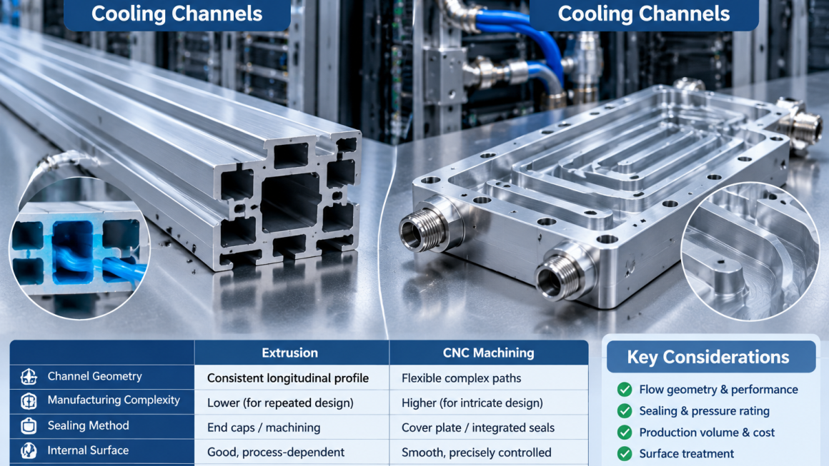
Aluminum extrusion forces heated aluminum billet through a shaped die to produce a continuous profile with a consistent cross-section.
For liquid-cooling applications, the extrusion die can create longitudinal internal passages, multiple parallel channels, ribs, and other repeated geometric features.
Typical applications include:
- Longitudinal cooling channels
- Multi-passage aluminum profiles
- Cooling rails and structural cooling sections
- Heat exchanger components
- Custom aluminum profiles for liquid-cooling assemblies
The main advantage is the ability to produce repeated channel geometry along the extrusion length.
However, extrusion is generally best suited to channels that follow the profile’s longitudinal direction. Complex branching passages, cross-drilled connections, and changing internal geometries usually require additional machining or assembly operations.
CNC-machined aluminum cooling channels
<AsyncImage query=”CNC machined aluminum liquid cooling cold plate internal milled coolant channels precision industrial manufacturing close up” aspectRatio=”16:9″ width=”100%” />
CNC machining removes material from an aluminum workpiece using controlled cutting tools.
For liquid-cooling hardware, channels can be machined into a plate, block, or other aluminum component. The geometry can include straight passages, pockets, manifolds, connection ports, and selected three-dimensional flow features.
Typical applications include:
- Cold plates
- Machined cooling blocks
- Liquid distribution manifolds
- Complex coolant passages
- Components with precision mounting and sealing interfaces
CNC machining offers greater flexibility for localized and changing geometries. However, deep, narrow, or enclosed passages can be difficult to machine, inspect, clean, and finish.
In many designs, machined channels are initially open and must be closed using a cover plate, brazing, welding, or another qualified joining method.
2. Extrusion vs. CNC Machining: Key Differences
The following table summarizes the main engineering and manufacturing differences.
| Evaluation factor | Aluminum extrusion | CNC machining |
|---|---|---|
| Basic geometry | Consistent longitudinal cross-section | Flexible geometry within machining access limits |
| Internal channels | Suitable for repeated straight passages | Suitable for machined pockets, passages, and ports |
| Complex branching | Usually requires secondary machining or assembly | More flexible for accessible branching features |
| Design changes | Changes to cross-section may require new or modified dies | CAD and toolpath changes may be sufficient |
| Tooling investment | Extrusion die required | Workholding and cutting tools required; no extrusion die |
| Material utilization | Efficient for repeated profile production | Material removed during machining |
| Dimensional control | Depends on die, alloy, extrusion process, and finishing | Depends on machine, fixturing, tools, and process control |
| Internal surface | Formed by extrusion die and process conditions | Influenced by cutting tools, toolpaths, and finishing |
| Sealing design | Often requires end closures, ports, or assembled interfaces | Depends on whether channels are open, enclosed, or covered |
| Production economics | Attractive for suitable designs at repeat volume | Often practical for prototypes, lower volumes, and complex parts |
| Typical applications | Extruded cooling profiles and repeated channel sections | Cold plates, manifolds, and complex machined components |
Neither process is universally superior. The correct choice depends on the cooling architecture and the component’s functional requirements.
3. Channel Geometry: What Can Each Process Manufacture?
Channel geometry is one of the most important factors when choosing between extrusion and CNC machining.
The coolant flow path determines the available cross-sectional area, hydraulic diameter, flow distribution, pressure drop, and heat-transfer behavior.
Extrusion: Repeated longitudinal passages
Extrusion is particularly suitable when the design uses a consistent cross-section along the component length.
For example, a profile may contain several parallel channels separated by internal walls. These passages can be formed during extrusion without machining every channel individually.
Potential design features include:
- Multiple parallel coolant passages
- Internal reinforcing ribs
- Integrated mounting features
- Uniform wall sections
- Repeated channel dimensions
- External heat-transfer features
However, extrusion die design has practical limits.
Extremely thin internal walls, narrow cavities, sharp transitions, and complicated hollow sections may increase die complexity and affect metal flow, dimensional consistency, and production stability.
The profile must be designed around both the required fluid geometry and extrusion feasibility.
CNC machining: More flexible localized geometry
CNC machining is useful when the coolant path requires features that cannot be produced efficiently through a constant extrusion cross-section.
Examples include:
- Cross-drilled passages
- Machined distribution pockets
- Multiple inlet and outlet ports
- Local changes in channel dimensions
- Precision sealing grooves
- Complex connection interfaces
CNC machining can also create channel patterns that vary across the component surface.
However, machining access must be considered. A tool cannot directly reach every enclosed or undercut feature, and deep narrow passages may create challenges for chip evacuation, tool deflection, and surface quality.
Engineering consideration
The best channel geometry is not necessarily the most complicated one.
Engineers should first define the required flow rate, coolant properties, inlet and outlet conditions, allowable pressure drop, heat load, and temperature limits.
The channel design can then be developed around the required thermal and hydraulic performance.
4. Manufacturing Complexity and Design Flexibility
The two processes have different cost structures and design constraints.
Extrusion requires early cross-section planning
A custom extrusion project generally involves die design, die manufacturing, process trials, and profile qualification.
Once the die is established, repeated production can be efficient. However, changes to the fundamental cross-section may require die modification or replacement.
This makes extrusion particularly suitable when the basic channel geometry is expected to remain stable across production.
Before releasing a profile for tooling, engineers should review:
- Wall thickness distribution
- Internal passage dimensions
- Die bearing and metal-flow considerations
- Profile straightness and twist
- Cutting length and end-face requirements
- Secondary machining operations
- Dimensional requirements after finishing
CNC machining supports iterative development
CNC machining can be more flexible during early development because channel dimensions and localized features can often be modified through revised CAD models and machining programs.
This is useful when the cooling design is still being optimized.
However, design flexibility does not mean every geometry is easy or economical to machine.
Deep pockets, narrow channels, long tool extensions, complex fixturing, and difficult chip evacuation can increase machining time and reduce process reliability.
A practical approach
For projects with changing requirements, CNC machining may be useful during initial development.
Once the basic flow geometry has been validated and production demand becomes more predictable, engineers can evaluate whether an extruded profile offers a better manufacturing route.
5. Sealing Design: A Critical Difference Between the Processes
A liquid-cooling channel must do more than provide a flow path. It must also maintain reliable containment under the specified operating conditions.
Sealing requirements should be considered during the initial component design rather than after the channel geometry is finalized.
Sealing extruded channels
Extruded hollow profiles can contain longitudinal passages, but their ends and connection points still need appropriate sealing arrangements.
Depending on the design, this may involve:
- End caps
- Machined inlet and outlet ports
- Gasket interfaces
- O-ring sealing features
- Qualified welding or brazing
- Other engineered closure methods
The sealing method must account for the profile geometry, coolant, operating pressure, temperature range, and expected service life.
The extrusion process itself does not guarantee a leak-tight finished cooling assembly.
Sealing CNC-machined channels
CNC-machined channels are often produced as open grooves or pockets in a plate or block.
A separate cover plate may be attached to close the passages.
Potential joining methods include:
- Brazing
- Welding
- Mechanical fastening with gaskets or O-rings
- Other qualified bonding or sealing processes
Each method has different implications for joint design, deformation, inspection, repairability, and production cost.
For example, a bolted cover plate with O-rings may support disassembly in some applications, but it requires suitable groove geometry, surface flatness, fastener arrangement, and controlled compression.
A brazed or welded construction may provide a more integrated assembly, but its process must be validated for the material, geometry, and operating conditions.
What should be evaluated?
The engineering team should define:
- Maximum operating pressure
- Required proof or qualification pressure
- Operating temperature range
- Coolant composition and compatibility
- Seal material compatibility
- Joint geometry and tolerances
- Pressure and leak-test acceptance criteria
A sealing design should be evaluated as part of the complete assembly, not just as an isolated aluminum channel.
6. Internal Surface Quality and Flow Performance
Internal surface characteristics can influence liquid-cooling performance, but surface appearance alone does not determine whether a channel is suitable.
Flow behavior depends on channel geometry, hydraulic diameter, surface condition, coolant properties, flow rate, and operating conditions.
Extruded channel surfaces
The internal surface of an extruded channel is formed by the extrusion die and process conditions.
Its characteristics may be influenced by:
- Die surface condition
- Alloy composition
- Extrusion speed and temperature
- Metal flow behavior
- Profile geometry
- Subsequent cleaning and finishing
An extruded channel may be suitable without extensive internal machining when its surface and dimensional requirements are compatible with the application.
However, engineers should not assume that every extruded internal passage will have the same surface finish or dimensional consistency.
CNC-machined channel surfaces
Machined channels contain surface features influenced by cutting tools, feed rates, toolpaths, and machining conditions.
CNC machining can provide controlled dimensions and selected surface finishes on accessible channel surfaces.
However, internal surface quality can become difficult to control in deep or narrow passages.
Machining also creates chips and cutting residues that must be removed before the component is assembled and placed into service.
Cleaning and contamination control
For both processes, cleanliness is essential.
Potential contamination sources include:
- Metal chips
- Machining fluids
- Abrasive particles
- Deburring residues
- Cleaning agents
- Assembly debris
The cleaning process should be appropriate for the coolant system and the component’s internal geometry.
Where channels cannot be directly inspected, the manufacturer may need a defined flushing, cleanliness verification, or other validated process.
The acceptance criteria should reflect the sensitivity of the cooling loop and its downstream components.
7. Dimensional Accuracy and Interface Requirements
Liquid-cooling components often contain interfaces that must connect accurately with hoses, fittings, manifolds, cold plates, or structural assemblies.
These interfaces may be more critical than the overall external dimensions.
Extruded components
Extrusion can provide repeatable profile geometry, but dimensions may vary within the applicable process and product tolerances.
Secondary machining may be needed for:
- End faces
- Mounting holes
- Threaded ports
- Precision connection interfaces
- Sealing surfaces
- Reference datums
Designers should distinguish between dimensions controlled by the extrusion process and features requiring machining.
CNC-machined components
CNC machining can produce accurate localized interfaces, subject to the capability of the equipment, fixturing, tooling, and inspection method.
It is especially useful for features that require precise positional relationships, such as port locations, O-ring grooves, mounting holes, and flat mating surfaces.
A useful design principle
Use extrusion for geometry that can be efficiently formed as a consistent profile.
Use CNC machining for features that require localized precision or cannot be formed economically through extrusion.
This approach can reduce unnecessary machining while preserving the accuracy of critical interfaces.
8. Pressure Testing and Leak Validation
Pressure and leak testing are important parts of liquid-cooling component qualification.
The appropriate test method depends on the component’s design, intended operating conditions, applicable standards, and customer requirements.
Extruded cooling assemblies
Testing may need to cover:
- The integrity of the extruded passage
- End closures
- Machined ports
- Welded or brazed joints
- Fittings and connection interfaces
- The complete assembled flow path
A profile that appears dimensionally acceptable may still leak at an end closure or connection.
CNC-machined cooling components
Testing should consider:
- Machined channel integrity
- Cover plate joints
- Brazed or welded areas
- O-ring or gasket interfaces
- Threaded ports
- The assembled coolant passage
The selected test method should be suitable for the component and its specified pressure rating.
Common validation methods
Depending on the design, validation may include:
- Pressure testing
- Hydrostatic testing
- Pneumatic leak testing under an approved safety procedure
- Helium leak testing for applications requiring higher leak sensitivity
- Flow testing
- Dimensional inspection
- Thermal performance testing
- Thermal cycling or pressure cycling qualification
These tests serve different purposes and are not interchangeable.
A pressure test evaluates behavior under a specified pressure condition. A leak test evaluates leakage against a defined acceptance criterion. A flow test evaluates hydraulic behavior. Thermal testing assesses performance under specified heat-load and operating conditions.
Passing one test does not automatically demonstrate that all other requirements have been satisfied.
9. Production Volume and Manufacturing Economics
Production quantity is another major factor in choosing between extrusion and CNC machining.
The two processes distribute manufacturing costs differently.
Extrusion: Tooling investment and repeat production
Custom extrusion requires a die, which introduces initial tooling costs and development time.
However, once the profile is qualified, repeated production can be efficient because the cross-section is formed continuously.
Extrusion becomes attractive when:
- The same profile is required repeatedly
- The cross-section is stable
- Channel geometry is suitable for extrusion
- Production volume justifies the die investment
- Secondary machining requirements are manageable
The economic advantage depends on profile size, alloy, die complexity, production length, material yield, finishing, and additional operations.
CNC machining: Flexibility and low initial tooling
CNC machining generally avoids the need for a custom extrusion die.
This can make it practical for:
- Early prototypes
- Engineering samples
- Low-volume production
- Complex localized geometries
- Designs with frequent revisions
However, machining time and material removal can become significant cost factors as quantities increase.
For high-volume production, extensive machining of features that could be incorporated into an extrusion may not be economical.
Compare total manufacturing cost
A realistic cost comparison should include more than the quoted unit price.
| Cost factor | Extrusion route | CNC machining route |
|---|---|---|
| Initial tooling | Custom extrusion die | Workholding and machining setup |
| Material utilization | Often efficient for repeated profiles | Depends on stock size and material removal |
| Processing time | Efficient for suitable repeated cross-sections | Depends on feature complexity and machining time |
| Secondary operations | May require machining, cutting, and closure assembly | May require cover joining, finishing, and cleaning |
| Design revisions | Cross-section changes can affect die investment | CAD, tooling, and program revisions may be required |
| Production scaling | Often attractive for stable, repeated geometry | Can become costly for highly machined high-volume parts |
The best choice should be based on total cost across the intended product lifecycle.
10. When to Choose Extrusion, CNC Machining, or a Hybrid Process
The decision should reflect the actual cooling architecture.
Choose extrusion when:
- The coolant passages run primarily along one direction.
- The cross-section remains consistent along the component length.
- Multiple parallel channels can be incorporated into the profile.
- The design is stable and expected to repeat.
- The expected production quantity supports the tooling investment.
- Secondary machining and sealing operations are manageable.
Choose CNC machining when:
- The cooling path requires localized or changing geometry.
- The component includes complex ports and manifolds.
- Precision sealing interfaces are essential.
- The project is still in an iterative development stage.
- Production quantities are relatively low.
- The geometry is unsuitable for efficient extrusion.
Consider a hybrid process when:
- The main cooling passage can be formed by extrusion.
- Ports and connection interfaces require CNC machining.
- The profile needs machined end faces or sealing features.
- A cover, end cap, or manifold must be joined to the extruded body.
- The design requires a balance between repeat production and geometric flexibility.
For many custom aluminum cooling channels, the hybrid approach may offer a practical balance between manufacturing efficiency and design flexibility.
11. Hybrid Manufacturing: Combining Extrusion and CNC Machining
<AsyncImage query=”precision aluminum extruded liquid cooling manifold profile with CNC machined ports and end connections industrial engineering product photography” aspectRatio=”16:9″ width=”100%” />
Extrusion and CNC machining do not have to be competing processes. They can be combined to create a more efficient manufacturing route.
A typical hybrid workflow may include:
- Design the primary longitudinal channel geometry.
- Manufacture the custom aluminum extrusion.
- Cut the profile to the required length.
- CNC-machine inlet and outlet ports.
- Machine mounting and sealing interfaces.
- Deburr and clean the internal passages.
- Install end closures or other joining components.
- Apply the specified surface treatment where appropriate.
- Conduct dimensional, pressure, leak, and flow validation.
This approach can reduce the amount of material removed through machining while preserving the ability to create precision interfaces.
However, the hybrid design introduces additional process-control requirements. The interface between extrusion and secondary machining must be carefully defined, and all closure and joining operations must be included in the validation plan.
For pressure-containing assemblies, the manufacturing sequence, joining process, inspection, and test requirements should be established before production.
12. Material Compatibility and Corrosion Considerations
Aluminum alloy selection is important for liquid-cooling applications.
The selected alloy should be evaluated for:
- Extrusion or machining suitability
- Mechanical properties
- Thermal conductivity
- Corrosion behavior
- Joining compatibility
- Surface treatment compatibility
- Coolant chemistry and operating conditions
Coolant compatibility should not be assumed based on the fact that a component is made from aluminum.
The coolant formulation, pH, inhibitors, temperature, dissolved oxygen, contaminants, and contact with other metals can all influence corrosion behavior.
Galvanic corrosion may also occur when aluminum is electrically connected to dissimilar metals in an electrolyte environment. The risk depends on the material combination and the actual system conditions.
Surface treatments may provide additional protection, but they do not replace coolant compatibility evaluation and appropriate system-level corrosion control.
For components with sealing surfaces, ports, or other critical interfaces, the finishing process should also be coordinated with the assembly design.
13. A Practical Manufacturing Selection Workflow
Before releasing a liquid-cooling component for production, engineering and procurement teams can use the following workflow.
Step 1: Define the operating requirements.
Establish heat load, coolant type, flow rate, inlet temperature, operating pressure, pressure limits, and allowable pressure drop.
Step 2: Develop the channel geometry.
Determine the required passage dimensions, number of channels, flow distribution, port positions, and sealing arrangement.
Step 3: Evaluate manufacturing feasibility.
Review whether the geometry is suitable for extrusion, CNC machining, or a combination of both.
Step 4: Define critical interfaces.
Identify ports, fittings, O-ring grooves, cover joints, mounting features, and surfaces requiring controlled dimensions or finishes.
Step 5: Prepare a prototype.
Manufacture representative samples and evaluate dimensional accuracy, assembly fit, internal cleanliness, and relevant functional performance.
Step 6: Validate the cooling component.
Conduct the agreed pressure, leak, flow, and thermal tests. Establish documented acceptance criteria for each test.
Step 7: Review production economics.
Compare tooling investment, machining time, material utilization, secondary operations, inspection, and expected production quantity.
Step 8: Establish production controls.
Finalize drawings, material specifications, process requirements, inspection plans, traceability, and engineering change procedures.
This process helps ensure that manufacturing decisions are based on both technical requirements and production realities.
14. Common Design and Manufacturing Mistakes
Several mistakes can increase manufacturing cost or compromise liquid-cooling reliability.
Choosing extrusion before confirming the flow path: A complicated manifold may require extensive secondary machining, reducing the economic advantage of extrusion.
Using CNC machining for every feature: Machining a repeated longitudinal profile from solid stock may create unnecessary material waste and processing time.
Ignoring channel accessibility: Deep or narrow passages can make chip removal, cleaning, and inspection difficult.
Treating a machined channel as a finished cooling component: Open channels require an engineered closure and sealing method.
Ignoring dimensional changes after finishing: Surface treatment can affect sealing grooves, mating surfaces, and precision interfaces.
Testing only the base component: The complete assembled coolant path may contain additional leakage risks at ports, closures, and joints.
Assuming all aluminum alloys behave identically: Alloy selection affects extrusion, machining, joining, mechanical properties, and corrosion performance.
Skipping pilot validation: A successful prototype does not automatically demonstrate stable production capability.
Addressing these issues during design and process planning can reduce avoidable revisions and improve manufacturing consistency.
Choosing between extruded and CNC-machined aluminum cooling channels is an engineering decision based on flow geometry, sealing architecture, manufacturing feasibility, quality requirements, and production quantity.
Extrusion is particularly suitable for repeated longitudinal passages and stable profile geometries. CNC machining provides greater flexibility for localized features, ports, manifolds, and precision interfaces. A hybrid process can combine the advantages of both when the cooling architecture requires repeated channel sections alongside complex connection features.
For aluminum cooling channel extrusion vs CNC machining, the most effective manufacturing route is the one that meets the hydraulic, thermal, mechanical, and sealing requirements while remaining practical to inspect, validate, and produce consistently.
At Aluminum4AI, custom aluminum cooling channels can be approached through application-focused profile development, extrusion feasibility review, CNC secondary machining, and manufacturing coordination. By considering process selection early, engineering teams can develop liquid-cooling hardware that is better aligned with both system requirements and production objectives.