

Why Profile Design Matters in AI Infrastructure
As AI data centers move toward higher computing density, more demanding structural requirements, and increasingly complex cooling architectures, the aluminum components surrounding servers must do more than provide basic mechanical support.
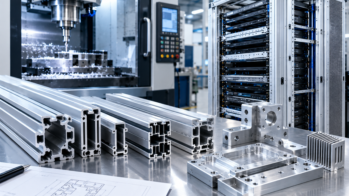
AI racks, server chassis, cooling equipment frames, cable management systems, and modular enclosures all depend on carefully designed structural interfaces. In many applications, custom aluminum extrusion provides an efficient way to create repeatable geometry while integrating mounting features, reinforcement, cable routing, and assembly interfaces into a single profile.
However, a successful extrusion project does not begin with a die or a material quotation. It begins with a clear understanding of the component’s function.
Custom aluminum extrusions for AI data centers must balance structural performance, profile geometry, extrusion feasibility, machining requirements, assembly accuracy, and production economics.
A profile that performs well in a CAD model may still be difficult to extrude, expensive to machine, or inconvenient to assemble. The most effective design process connects engineering requirements with manufacturing capabilities from the beginning.
This guide explains the main steps involved in developing custom aluminum extrusions for AI infrastructure, from cross-sectional design and alloy selection to die development, CNC machining, inspection, and production scaling.
1. Define the Application Before Designing the Profile
The first step is to identify what the extrusion must do within the larger system.
Different AI infrastructure components require different profile characteristics.
Common applications include:
- AI server rack frames and vertical posts
- Horizontal structural beams
- GPU server chassis and mounting rails
- Modular equipment enclosure frames
- Cable routing channels and trays
- Liquid cooling equipment supports
- Heat sink profiles
- Brackets and interfaces for cooling assemblies
- Edge AI equipment enclosures
A structural rack member may require high bending stiffness and reliable fastener connections. A cable channel may prioritize routing capacity, accessibility, and installation flexibility. A heat sink profile must consider fin geometry, heat transfer, and airflow resistance.
Before developing the cross-section, define the following requirements.
Mechanical requirements
- Expected load and load direction
- Maximum allowable deflection
- Unsupported span
- Connection and fastening method
- Vibration or repeated loading conditions
Integration requirements
- Mounting slots and hole positions
- Interfaces with adjacent profiles
- Cable and hose routing
- Access for tools and fasteners
- Required adjustment or modularity
Manufacturing requirements
- Target dimensions and tolerances
- Alloy and temper
- Surface treatment
- CNC machining features
- Initial and forecast production quantities
These requirements establish the design priorities and help determine whether a standard profile, a modified extrusion, or a completely custom cross-section is appropriate.
2. Design the Cross-Section Around Function
The cross-section is the foundation of an aluminum extrusion.
Unlike a machined component, which can be produced by removing material from a solid block, extrusion creates a continuous profile through a die. The cross-sectional geometry therefore has a direct influence on structural behavior, manufacturing feasibility, and material utilization.
For AI rack aluminum profiles, a well-designed cross-section can combine several functions in one component.
For example, a single profile might provide:
- Structural stiffness
- Mounting slots for rack accessories
- Fastener channels
- Cable routing space
- Interfaces for removable panels
- Attachment points for cooling brackets
Integrating these features can reduce the number of separate parts and simplify assembly.
Use Geometry to Improve Stiffness
Structural performance depends on the alloy, cross-sectional area, material distribution, support conditions, and loading.
For a beam under bending, material positioned farther from the neutral axis can contribute disproportionately to bending stiffness. This is why section depth, flanges, and appropriately designed ribs can be more effective than increasing wall thickness uniformly.
Depending on the application, designers may consider:
- Deeper sections for improved bending stiffness
- Flanges to increase section efficiency
- Internal ribs to reinforce selected regions
- Closed or partially enclosed sections to improve torsional behavior
- Local reinforcement around mounting interfaces
These features must be evaluated against extrusion constraints and the required load cases.
More material does not automatically create a better profile. A well-optimized cross-section can sometimes deliver the required stiffness with less material and lower overall weight.
Avoid Unnecessary Complexity
Every additional feature may affect die design, extrusion flow, dimensional control, machining, and cost.
The objective is not to create the most complicated profile possible. It is to create the simplest manufacturable geometry that meets the functional requirements.
3. Optimize Wall Thickness and Feature Transitions
Wall thickness is one of the most important factors in custom extrusion design.
Excessively thin walls may be difficult to extrude consistently, depending on the alloy, section size, feature arrangement, and extrusion equipment. Very thick regions may create uneven cooling and dimensional variation, while abrupt changes in thickness can complicate material flow.
The appropriate wall thickness depends on several interacting variables:
- Overall profile dimensions
- Alloy and temper
- Extrusion press capability
- Die design
- Local feature geometry
- Required dimensional tolerances
- Mechanical loads
- Surface quality requirements
There is no single wall-thickness value suitable for every AI rack aluminum profile.
Maintain Reasonable Thickness Transitions
Where possible, avoid abrupt changes between very thin and very thick regions.
Gradual transitions can help make the section more practical to manufacture and may reduce local stress concentrations in service.
Internal corners should also be designed with suitable radii rather than unnecessarily sharp geometry.
The final dimensions must be confirmed with the extrusion manufacturer because feasible wall thickness and radius values vary with the profile and process.
Reinforce Critical Areas Selectively
Mounting holes, threaded features, and attachment points may require additional material or local reinforcement.
Instead of making the entire profile heavier, designers can reinforce the regions that carry concentrated loads.
For example, a rack extrusion may use a relatively lightweight main section with additional material around the channels used to attach heavy equipment.
The reinforced region must still remain compatible with extrusion, machining, fastener access, and the overall load path.
4. Design T-Slots and Mounting Interfaces Carefully
T-slots and similar mounting channels are widely used in modular aluminum framing because they allow components to be attached, adjusted, and replaced.
In AI infrastructure, mounting interfaces may support:
- Rack accessories
- Cable trays
- Equipment panels
- Cooling brackets
- Sensors and monitoring devices
- Internal support rails
- Modular structural cross-members
Their usefulness depends on the intended connection and the loads involved.
Define the Interface Requirements
Before specifying a T-slot or mounting channel, determine:
- Required fastener or nut type
- Fastener insertion method
- Available tool clearance
- Required adjustment range
- Connection loads
- Expected number of assembly cycles
- Access for installation and maintenance
A slot that is easy to manufacture may still be inconvenient if fasteners cannot be inserted after adjacent components are installed.
Likewise, a mounting channel intended for heavy structural loads may need a different design from one used for lightweight accessories.
Consider Standardization
Standardized mounting interfaces can support reuse across multiple rack configurations.
For example, a common profile family may be used across several equipment heights, with different cross-members, panels, and brackets added as needed.
Standardization can reduce the number of unique components and simplify future modifications. However, the interface dimensions, load capacity, and connection method must be controlled to ensure repeatable assembly.
A modular profile is only as useful as the connection system built around it.
5. Select the Alloy and Temper for the Manufacturing Route
Alloy selection should be coordinated with extrusion geometry and the component’s mechanical requirements.
Two commonly considered alloys are 6061 and 6063, but their suitability depends on the specific application and specified temper.
6063 Aluminum for Extruded Profiles
6063 is widely used for architectural and industrial extrusions, including profiles where surface appearance and cross-sectional detail are important.
Potential AI infrastructure applications include:
- Modular rack profiles
- Equipment frame members
- Cable management channels
- Enclosure structures
- Selected heat sink profiles
6061 Aluminum for Structural and Machined Applications
6061 is commonly used for structural components and CNC-machined parts where a useful combination of strength and machinability is required.
Depending on the design, it may be considered for:
- Structural mounting components
- Machined brackets
- Precision interface parts
- Custom components requiring secondary machining
Both alloys can be used in a range of applications, but the selection must account for the specified temper, mechanical requirements, extrusion feasibility, surface treatment, and subsequent machining.
The strongest material on paper is not automatically the best choice if it makes the required profile difficult to manufacture or does not offer a meaningful benefit for the application.
6. Evaluate Extrusion Die Feasibility Early
A custom aluminum extrusion requires a die designed around the cross-section and manufacturing process.
Die design is influenced by profile complexity, material flow, section dimensions, wall-thickness distribution, and production requirements.
Certain geometries are more challenging to extrude than others.
Examples include:
- Very thin walls relative to the overall profile size
- Narrow or deep cavities
- Complex hollow sections
- Uneven material distribution
- Small internal radii
- Features that are difficult to support during extrusion
Hollow profiles may require specialized die configurations. Their feasibility and cost depend on the specific section, tooling design, and production setup.
Conduct a Design-for-Extrusion Review
Before committing to tooling, review the profile with the extrusion manufacturer.
Key questions include:
- Can the required cross-section be extruded reliably?
- Are the wall thicknesses and transitions practical?
- Can the specified alloy and temper meet the mechanical requirements?
- Which dimensions can be held directly by extrusion?
- Which features should be produced through CNC machining?
- What straightness, twist, and dimensional tolerances are realistic?
- What tooling investment and lead time are expected?
Early review may identify opportunities to simplify the cross-section without compromising its function.
It can also prevent a common problem: finalizing a profile based entirely on engineering geometry before checking whether it can be produced consistently.
7. Decide Which Features Belong in Extrusion and Which Require CNC Machining
Extrusion is well suited to creating continuous cross-sectional features. CNC machining is better suited to many localized precision features.
Combining the two processes is often an effective strategy for custom aluminum hardware.
Features Commonly Created by Extrusion
- Main profile geometry
- Continuous ribs and flanges
- Longitudinal channels
- Mounting grooves
- Cable routing cavities
- Continuous fin arrays
- Repeated cross-sectional interfaces
Features Commonly Added Through CNC Machining
- Cross-holes
- Threaded holes
- Localized mounting slots
- Precision end faces
- Connector openings
- Counterbores and countersinks
- Critical mating surfaces
- Custom assembly interfaces
For example, an AI rack beam may be extruded with integrated mounting channels and reinforcing ribs. After cutting to length, CNC machining can create the holes and end features required for assembly.
This approach can reduce material waste compared with machining the entire component from a solid block.
Minimize Unnecessary Machining
CNC machining adds cost through machine time, fixtures, tool changes, inspection, and material removal.
Where practical, use the extrusion to create functional geometry that can be maintained consistently over the profile length.
However, extrusion should not be forced to produce every feature. If a dimension is critical to sealing, alignment, or thermal contact, secondary machining may be necessary.
The best process plan balances geometric efficiency with functional precision.
8. Establish Tolerances Based on Assembly and Function
Extrusion tolerances and machining tolerances serve different purposes.
Extruded profiles are affected by factors such as section geometry, cooling, stretching, cutting, and process variation. CNC machining can provide tighter control over selected features, depending on the equipment, setup, and inspection method.
The drawing should identify which dimensions are critical to the final assembly.
Examples include:
- Rail mounting locations
- Hole-to-hole distances
- Profile interfaces
- Panel alignment features
- Precision bracket connections
- Surfaces that contact cooling components
Not every dimension requires the tightest achievable tolerance.
Over-specifying tolerances may increase tooling, machining, inspection, and rejection costs without improving system performance.
A practical tolerance strategy distinguishes between:
- General profile dimensions
- Critical assembly interfaces
- Machined precision features
- Cosmetic dimensions
- Features that affect structural or thermal performance
For multi-component assemblies, tolerance stack-up analysis can help determine whether individual parts will fit and align as intended.
9. Plan Surface Treatment Around the Final Application
Surface treatment can affect corrosion resistance, appearance, wear, electrical contact, and dimensional fit.
Common options for aluminum infrastructure components include anodizing, conversion coatings, and other application-specific protective finishes.
The appropriate treatment depends on the operating environment and component function.
For example, a visible enclosure profile may prioritize appearance and corrosion protection. A structural component may require protection against handling and environmental exposure. A precision thermal interface may need carefully defined contact areas.
Before selecting the finish, consider:
- Indoor or outdoor operation
- Exposure to moisture and contaminants
- Required appearance
- Electrical grounding and bonding
- Thermal contact surfaces
- Assembly clearances
- Masking requirements
- Compatibility with adjacent materials
Where aluminum connects with copper or other dissimilar metals, corrosion compatibility should be evaluated at the system level.
Surface treatment should be planned before production rather than added as an afterthought, because it can affect dimensions, assembly, and inspection.
10. Validate the Profile Before Scaling Production
A successful first extrusion does not automatically prove that the component is ready for large-scale deployment.
Validation should confirm that the profile meets its dimensional, mechanical, and functional requirements.
Depending on the application, checks may include:
Dimensional inspection
- Cross-sectional dimensions
- Wall thickness
- Straightness
- Twist
- Cut length
- Critical machined features
Material verification
- Alloy and temper
- Required material documentation
- Mechanical properties where specified
Surface inspection
- Scratches, dents, and visible defects
- Surface treatment consistency
- Relevant cosmetic requirements
Structural validation
- Load capacity
- Deflection
- Connection strength
- Vibration or repeated loading where required
Assembly validation
- Fastener access
- Fit with mating components
- Alignment
- Interference checks
- Maintenance access
For thermal profiles, additional testing may be needed to verify heat-transfer performance under the intended operating conditions.
Testing should follow documented acceptance criteria. Not every profile needs every test; the validation plan should reflect the component’s role and risk.
11. Scale from Prototype to Repeatable Production
Custom extrusion projects commonly progress through prototype development, pilot production, and larger production runs.
Each stage has a different purpose.
Prototype Stage
The main goal is to verify the geometry and functional concept.
Where tooling investment is not yet justified, an existing profile with secondary machining or a machined prototype may help evaluate fit and interfaces. However, a prototype made by a different process cannot fully establish the behavior or quality of the final extruded profile.
Pilot Production
Pilot production helps verify the manufacturing process and the assembled component.
Typical objectives include:
- Confirming profile consistency
- Checking machining repeatability
- Validating surface treatment
- Establishing inspection procedures
- Evaluating assembly fit
- Identifying process-related variation
Production Stage
For larger quantities, the project may benefit from dedicated tooling, optimized cutting and machining setups, standardized inspection, and controlled production documentation.
Production readiness should include clear drawings, approved samples where appropriate, defined acceptance criteria, and a process for managing engineering changes.
Consider Total Project Cost
The lowest quoted price per meter is not necessarily the lowest overall cost.
A meaningful comparison should consider:
- Die and tooling investment
- Minimum order quantities
- Material utilization
- CNC machining time
- Surface treatment
- Inspection requirements
- Scrap and rework risk
- Packaging and logistics
- Forecast production volume
The right manufacturing strategy depends on both the engineering requirements and the expected production lifecycle.
12. Common Mistakes in Custom Extrusion Design
Designing the Profile Without Manufacturing Input
A cross-section may look efficient in CAD but prove difficult to extrude consistently.
Better approach: Review the profile with the manufacturer before finalizing the tooling design.
Using Uniformly Thick Walls Everywhere
This can add unnecessary material and weight without proportionate structural benefits.
Better approach: Distribute material according to the load path, stiffness requirements, and extrusion feasibility.
Adding Too Many Unique Interfaces
Excessive profile variants can increase tooling, inventory, and assembly complexity.
Better approach: Standardize common interfaces and customize only where application requirements justify it.
Expecting Extrusion to Produce Every Precision Feature
Some localized features are more practical to machine after extrusion.
Better approach: Separate continuous profile geometry from precision features.
Specifying Tight Tolerances Without a Functional Reason
Overly restrictive tolerances may increase costs and complicate production.
Better approach: Identify critical-to-function dimensions and assign tolerances accordingly.
Scaling Production Before Validating Assembly
A profile can meet its drawing dimensions but still create interference or maintenance problems in the complete system.
Better approach: Validate fit, assembly, and serviceability before committing to larger production volumes.
13. A Practical Workflow for Custom Aluminum Extrusions
A structured development process helps align engineering and manufacturing.
Step 1 — Define the application
Identify the component’s role, load cases, interfaces, and operating environment.
Step 2 — Establish the requirements
Specify material, stiffness, dimensions, tolerances, surface treatment, and quantity.
Step 3 — Develop the cross-section
Optimize wall thickness, ribs, slots, cavities, and mounting features.
Step 4 — Review extrusion feasibility
Confirm that the geometry is compatible with the proposed alloy, tooling, and extrusion process.
Step 5 — Plan secondary machining
Identify holes, threads, end features, and precision interfaces.
Step 6 — Define inspection and testing
Set measurable acceptance criteria before production.
Step 7 — Produce and validate samples
Confirm dimensional accuracy, assembly fit, and functional performance.
Step 8 — Establish pilot production
Verify process repeatability and inspection methods.
Step 9 — Scale production
Optimize tooling utilization, machining efficiency, quality controls, and delivery planning.
This workflow helps reduce the risk of expensive redesigns and supports a smoother transition from custom engineering to repeatable manufacturing.
A Successful Extrusion Connects Design with Production
Custom aluminum extrusions provide an effective way to create structural and functional components for AI data center infrastructure.
Their value comes from more than the aluminum alloy itself. It comes from the interaction between cross-sectional geometry, wall thickness, reinforcement, mounting interfaces, extrusion tooling, CNC machining, surface treatment, and final assembly.
For AI rack aluminum profiles, the best design is not necessarily the most complex or the lightest. It is the profile that meets its mechanical and integration requirements while remaining manufacturable, inspectable, and economical at the intended production volume.
At Aluminum4AI, custom aluminum component development can connect profile design, extrusion feasibility, CNC machining, surface treatment, quality inspection, and prototype-to-production planning for AI infrastructure applications.
From profile design to production, successful aluminum extrusion begins with engineering requirements and ends with a component that works reliably in the complete system.