As AI server power density continues to increase, liquid cooling is becoming an increasingly important part of modern data center infrastructure.
However, liquid cooling is not simply a thermal-management problem.
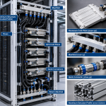
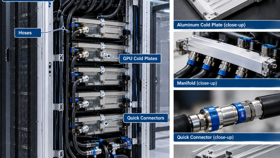
Once coolant enters an AI rack, a network of mechanical components must work together:
Cold Plates + Manifolds + Hoses + Quick Connectors + Structural Profiles + Mounting Brackets
The reliability of the cooling system therefore depends not only on heat-transfer performance, but also on how these components are mechanically supported and interconnected.
This is where aluminum structure for liquid cooling becomes important.
A well-designed aluminum structure can provide support for cooling components while also controlling alignment, vibration, thermal expansion, hose routing, and maintenance access.
The objective is not simply to attach a cooling system to an aluminum frame.
It is to design the structural architecture around the liquid-cooling interfaces from the beginning.
Why Liquid Cooling Requires Structural Integration
In an air-cooled server, many components can be mounted relatively independently.
Liquid cooling introduces additional mechanical interfaces.
A typical AI rack may contain:
- GPU cold plates
- Coolant manifolds
- Supply hoses
- Return hoses
- Quick-disconnect connectors
- Pumps
- Distribution units
- Valves
- Leak detection components
- Structural supports
Each component has its own weight, dimensional requirements, and movement characteristics.
The cooling system also experiences:
- Pressure
- Temperature changes
- Thermal expansion
- Vibration
- Hose movement
- Maintenance loads
These forces eventually need to be transferred into the rack structure.
A simplified load path can be represented as:
Cold Plate → Hose / Connector → Manifold → Mounting Bracket → Aluminum Profile → Rack Frame
If any interface in this chain is poorly designed, the resulting stress can affect the reliability of the complete cooling system.
The Role of an Aluminum Structure for Liquid Cooling
An aluminum structure can perform several functions simultaneously.
It can provide:
- Mechanical support
- Alignment
- Equipment mounting
- Hose routing
- Connector positioning
- Cable management
- Thermal support
- Service access
This makes aluminum extrusion particularly attractive for modular liquid-cooled AI infrastructure.
A properly engineered profile can incorporate mounting channels, structural ribs, and attachment features directly into its cross-section.
Instead of adding numerous independent brackets, the structural profile can become an integrated mounting platform.
Start With the Cooling Interface, Not the Profile
One common design mistake is to select a standard aluminum profile first and then attempt to fit the cooling components around it.
For liquid-cooled AI systems, the design sequence can be more effective when reversed.
Start with:
Cold Plate → Connector → Hose → Manifold
Then define:
Mounting Requirements → Load Paths → Structural Profile
This approach ensures that the aluminum structure supports the actual cooling architecture.
Important interface information may include:
- Connector dimensions
- Hose diameter
- Minimum bend radius
- Manifold weight
- Cold plate mounting points
- Required service clearance
- Operating temperature
- Pressure
- Expected thermal movement
The structural profile can then be optimized around these requirements.
Cold Plate Mounting
The cold plate is one of the most important interfaces in an AI liquid-cooling system.
It must maintain reliable thermal contact with the processor while being mechanically supported.
Depending on the architecture, the cold plate may experience:
- Mounting force
- Coolant pressure
- Thermal expansion
- Hose reaction forces
- Vibration
The supporting structure should therefore avoid transferring unnecessary mechanical loads into the processor package.
The design should clearly distinguish between:
Thermal Contact Loads
and
Structural Support Loads
A well-designed aluminum support structure can help maintain alignment without over-constraining the cold plate.
Manifold Support
The manifold distributes coolant to multiple cooling branches.
For example:
Main Supply → Manifold → Multiple Cold Plates
and:
Multiple Cold Plates → Return Manifold → Main Return
As the number of cooling branches increases, manifold weight and connection density can also increase.
The manifold should therefore have dedicated structural support.
A support structure may need to withstand:
- Manifold weight
- Internal pressure
- Hose reaction forces
- Connector insertion forces
- Thermal expansion
- Maintenance loads
The aluminum structure should support the manifold without introducing excessive stress into its ports or seals.
Why Connector Support Matters
Quick-disconnect connectors are designed to make maintenance easier.
However, they can also introduce mechanical loads.
Connecting or disconnecting a coupling requires physical force.
If the connector is supported only by a hose or thin manifold wall, this force can be transferred into sensitive components.
A better architecture can provide a structural mounting point close to the connector.
This creates a clearer load path:
Operator Force → Connector Support → Aluminum Structure
rather than:
Operator Force → Hose → Manifold → Cold Plate
This can improve serviceability and reduce unnecessary loading on the fluid system.
Quick Connectors and Alignment
Quick connectors require appropriate alignment during installation.
Poor alignment can make connection difficult and may increase mechanical stress.
An aluminum support profile can provide:
- Fixed connector locations
- Alignment features
- Mounting slots
- Structural stiffness
- Service clearance
For modular AI racks, this can make connector positioning more repeatable.
The structural system should allow the connector to move only where movement is intended.
Hose Routing Is a Structural Design Issue
Hoses are flexible, but they still need controlled routing.
A poorly routed hose can:
- Interfere with server components
- Reduce airflow around other equipment
- Experience excessive bending
- Place force on connectors
- Complicate maintenance
- Increase the risk of abrasion
The aluminum structure can provide dedicated routing paths.
These may include:
- Cable and hose channels
- Routing brackets
- Clamps
- Guide rails
- Protective edges
- Bend-radius supports
The objective is not to make every hose completely rigid.
It is to provide controlled flexibility.
Minimum Bend Radius
Liquid-cooling hoses typically have a specified minimum bend radius.
If the hose is bent too tightly, it may experience:
- Kinking
- Increased pressure drop
- Mechanical fatigue
- Connector loading
- Reduced service life
Therefore, the aluminum structure should be designed around the hose’s required bend radius.
This is a good example of why the structural profile cannot be designed independently from the cooling system.
A mounting channel that looks efficient on paper may be unsuitable if it forces the hose into an excessively tight bend.
Avoiding Hose-Induced Connector Loads
One of the most important principles in liquid-cooling structural design is:
Do not allow hose weight and hose movement to become unnecessary connector loads.
A long hose can create a moment around its connection point.
The problem can become more significant when:
- The hose is heavy
- The hose is long
- The bend is tight
- The connector is cantilevered
- The rack experiences vibration
A nearby aluminum support can carry part of the hose load.
This allows the connector to focus primarily on its intended fluid function rather than acting as a structural support.
Thermal Expansion of the Cooling Structure
Liquid cooling creates temperature changes throughout the rack.
Aluminum profiles can expand and contract as their temperature changes.
The same is true for:
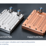
- Copper cold plates
- Stainless-steel connectors
- Steel brackets
- Polymer hoses
- Sealing materials
These materials have different thermal expansion characteristics.
Rigidly connecting everything together can therefore create unwanted mechanical stress.
A better structural design may use:
- Fixed mounting points
- Floating mounting points
- Sliding interfaces
- Flexible hose sections
- Expansion allowances
This allows the cooling architecture to accommodate predictable thermal movement.
Fixed and Floating Mounting
A long aluminum cooling support structure can benefit from a fixed-and-floating mounting strategy.
The fixed point establishes the reference position.
The floating points allow controlled thermal movement.
For example:
Fixed Mount → Controls Manifold Position
Floating Mount → Accommodates Aluminum Expansion
This approach can reduce thermal stress while maintaining system alignment.
The exact design depends on the rack dimensions and operating temperature range.
Pressure Loads and Structural Support
Liquid cooling systems operate under internal fluid pressure.
Although the coolant pressure may be contained primarily within the fluid components, pressure can still create mechanical forces at:
- Manifold connections
- Hose interfaces
- Quick connectors
- Seals
- Mounting points
The aluminum support system should therefore consider the reaction forces generated by the fluid network.
The structural design should not assume that the cooling components are mechanically neutral.
Vibration and Dynamic Loads
AI data center infrastructure may contain pumps, fans, valves, and other moving components.
These can introduce vibration.
Hoses and manifolds can also respond dynamically to pressure fluctuations or pump operation.
The aluminum structure should therefore provide sufficient stiffness to prevent excessive movement.
Potential design considerations include:
- Profile stiffness
- Bracket spacing
- Fastener selection
- Vibration isolation
- Hose support
- Manifold support
A lightweight structure should still maintain adequate dynamic stability.
Aluminum Profile Geometry
The cross-section of the aluminum profile plays an important role in structural performance.
An optimized extrusion can incorporate:
- Hollow chambers
- Internal ribs
- T-slots
- Mounting grooves
- Reinforcement sections
- Hose-support features
- Connector mounting points
This can create a multifunctional structural component.
Instead of:
Frame + Bracket + Hose Holder + Connector Mount
the design may potentially use:
Integrated Aluminum Cooling Support Profile
This can reduce component count and simplify assembly.
Structural Stiffness Around Cooling Interfaces
Strength alone is not sufficient.
The structure must also be stiff enough to maintain alignment.
Excessive deformation can affect:
- Cold plate positioning
- Manifold alignment
- Connector engagement
- Hose routing
- Service access
Therefore, engineers should evaluate both:
Structural Strength
and
Structural Stiffness
For precision cooling interfaces, stiffness may be the more important design criterion.
Aluminum Support for Manifolds
Manifolds are particularly suitable for dedicated aluminum support structures.
A structural extrusion can provide multiple mounting points along its length.
This allows the manifold to be supported at several locations rather than acting as a long cantilever.
The result can be:
Lower Bending → Better Alignment → Lower Connector Stress
The mounting system should also provide sufficient clearance for inspection and maintenance.
Designing Around Quick-Disconnect Maintenance
Liquid cooling systems must eventually be serviced.
Servers may need to be removed.
Cold plates may require replacement.
Hoses may need to be disconnected.
Quick connectors may need inspection.
Therefore, the aluminum support system should not obstruct service operations.
Engineers should consider:
- Connector access
- Tool clearance
- Hose movement
- Hand clearance
- Component removal paths
- Replacement space
A compact design is not necessarily a good design if technicians cannot access the interfaces.
Cable and Hose Integration
AI racks contain both electrical cables and cooling hoses.
These systems should be routed so that they do not interfere with each other.
An aluminum extrusion can potentially provide separate routing zones.
For example:
Upper Channel → Power / Communication Cables
Lower Channel → Cooling Hoses
or another configuration according to the rack architecture.
Physical separation can help improve:
- Organization
- Serviceability
- Protection
- Installation efficiency
It also allows the structural design to manage both electrical and fluidic infrastructure.
Protecting Hoses From Aluminum Structures
Aluminum is structurally robust, but sharp edges or poorly finished interfaces can damage flexible hoses.
Therefore, the aluminum profile should consider:
- Edge radius
- Surface finish
- Clamp design
- Protective inserts
- Hose contact points
The goal is to prevent:
Abrasion + Cutting + Excessive Compression + Repeated Bending
This becomes increasingly important in long-life installations.
Corrosion and Material Compatibility
Liquid cooling can involve multiple materials.
An AI cooling system may contain:
- Aluminum
- Copper
- Stainless steel
- Brass
- Polymer hoses
- Elastomer seals
The structural design should therefore consider material compatibility.
This includes both:
Galvanic Corrosion
and
Coolant Compatibility
For aluminum structures located near cooling interfaces, surface treatment and material isolation may be appropriate depending on the environment.
The structural system should be designed together with the cooling-fluid specification rather than independently.
Leak Detection and Structural Design
Leak detection is an important consideration in liquid-cooled AI infrastructure.
A structural profile should not obstruct areas where leaks need to be detected.
For example, drainage paths or inspection zones may be incorporated into the surrounding structure.
An aluminum support system can potentially provide:
- Controlled routing
- Inspection access
- Drainage clearance
- Sensor mounting
- Protective barriers
The objective is to make abnormal conditions easier to identify and manage.
Drainage and Condensation Considerations
Depending on operating conditions, condensation can become a concern.
Structural components should avoid creating unintended water-trapping areas.
An engineered aluminum extrusion can incorporate drainage or clearance features where appropriate.
Good structural design should consider:
Water Ingress → Drainage → Inspection → Maintenance
rather than focusing only on mechanical strength.
Manufacturing Aluminum Cooling Supports
Aluminum extrusion is well suited to modular liquid-cooling structures.
A typical manufacturing process can include:
Profile Design → Aluminum Extrusion → Cutting → CNC Machining → Surface Treatment → Inspection → Assembly
Extrusion creates the main structural geometry.
CNC machining can then provide:
- Precision mounting holes
- Connector interfaces
- Manifold attachment points
- Alignment features
- Threaded holes
This combination can provide both efficient material utilization and precision where required.
Designing for Different Production Volumes
The manufacturing strategy should also reflect production volume.
For prototype and low-volume AI infrastructure:
Extrusion + CNC Machining
can provide useful flexibility.
For larger production volumes:
Optimized Extrusion + Automated Cutting + Secondary Machining
may improve production efficiency.
The key is to design the profile and manufacturing process together.
A profile that is unnecessarily complex may increase tooling and machining costs without providing meaningful system benefits.
Thermal and Structural Simulation
Complex liquid-cooling structures may benefit from combined analysis.
Thermal simulation can evaluate:
- Temperature distribution
- Thermal gradients
- Heat transfer
Structural analysis can evaluate:
- Stress
- Deflection
- Mounting loads
- Vibration
- Thermal deformation
Fluid analysis can evaluate:
- Pressure
- Flow distribution
- Pressure drop
These analyses should not always be treated as independent.
A change in one area can influence another.
For example:
Higher Coolant Flow → Different Pressure → Different Hose Reaction Forces → Different Structural Loading
This demonstrates why system-level engineering is important.
A Practical Liquid-Cooling Structural Design Workflow
A practical development process can follow these steps.
Step 1: Define the Cooling Architecture
Identify cold plates, manifolds, hoses, connectors, and coolant paths.
Step 2: Define Interface Requirements
Document dimensions, mounting points, pressure, temperature, hose diameter, and connector requirements.
Step 3: Map Mechanical Loads
Identify component weight, pressure forces, hose forces, connector loads, and vibration.
Step 4: Design the Aluminum Support Structure
Develop extrusion profiles, brackets, and mounting interfaces around the cooling architecture.
Step 5: Address Thermal Expansion
Define fixed and floating mounting points.
Step 6: Integrate Hose and Cable Routing
Provide appropriate channels, supports, bend radius, and service clearance.
Step 7: Perform Simulation
Evaluate structural stiffness, thermal deformation, and critical interfaces.
Step 8: Prototype
Build representative cooling and structural assemblies.
Step 9: Test
Validate mechanical alignment, connector performance, hose routing, thermal behavior, and leak resistance.
Step 10: Optimize for Production
Finalize extrusion tooling, machining, surface treatment, inspection, and assembly processes.
Common Design Mistakes
Several problems can occur when liquid cooling is added to an existing rack structure.
Mistake 1: Supporting the Manifold Only at the Ends
A long manifold may experience unnecessary bending.
Mistake 2: Allowing Hoses to Load Connectors
Poor hose routing can create excessive mechanical stress.
Mistake 3: Rigidly Constraining Thermal Expansion
This can create thermal stress during temperature changes.
Mistake 4: Ignoring Maintenance Clearance
A compact structure may become difficult to service.
Mistake 5: Using Generic Profiles Without Interface Optimization
Standard profiles may not provide the required connector or manifold support.
Mistake 6: Treating Thermal and Structural Design Separately
Cooling performance and mechanical reliability are closely connected.
Designing Aluminum Cooling Support for Long-Term Reliability
A liquid-cooling structure may remain in operation for many years.
During that time it can experience:
- Repeated thermal cycling
- Vibration
- Mechanical maintenance
- Connector insertion and removal
- Hose movement
- Environmental exposure
- Structural loading
Therefore, long-term reliability should be considered during the initial design.
A good structure should maintain:
Alignment + Stiffness + Corrosion Resistance + Serviceability
throughout its intended lifecycle.
From Structural Profile to Integrated Cooling Platform
The future of AI rack design is moving toward greater integration.
Instead of treating the aluminum frame and cooling system as separate assemblies, engineers can design them together.
An integrated platform may combine:
Structural Support + Manifold Mounting + Hose Routing + Connector Positioning + Cable Management
within a coordinated aluminum architecture.
This can reduce component count and improve installation efficiency.
More importantly, it can create predictable mechanical relationships between the cooling system and the rack.
What Engineers Should Specify for an Aluminum Cooling Structure
When developing an aluminum structure for liquid cooling, the following information should ideally be defined early:
Structural Requirements
- Total load
- Mounting locations
- Required stiffness
- Vibration conditions
- Safety factor
Cooling Requirements
- Cold plate dimensions
- Manifold dimensions
- Hose diameter
- Connector type
- Operating pressure
- Operating temperature
- Coolant specification
Interface Requirements
- Connector alignment
- Hose bend radius
- Fastener requirements
- Thermal expansion allowance
- Service clearance
Manufacturing Requirements
- Aluminum alloy
- Extrusion profile
- Machining tolerance
- Surface treatment
- Production volume
- Inspection requirements
Defining these parameters early can significantly reduce redesign later in the development process.
Designing an aluminum structure for liquid cooling requires more than attaching cooling components to a conventional rack.
The structural system must be designed around the mechanical relationships between:
Cold Plates + Manifolds + Hoses + Quick Connectors + Aluminum Profiles
Each interface can introduce weight, pressure, movement, vibration, thermal expansion, or maintenance forces.
A well-engineered aluminum cooling support structure can provide:
Structural Support + Precise Alignment + Hose Management + Connector Support + Thermal Expansion Control + Serviceability
Aluminum extrusion is particularly useful because the profile geometry can be customized around the actual cooling architecture.
Mounting channels, reinforcement ribs, connector interfaces, hose-routing features, and structural supports can potentially be integrated into a single profile system.
The most effective design philosophy is therefore:
Cooling Architecture → Interface Definition → Load-Path Analysis → Aluminum Structure → Thermal-Mechanical Design → Prototype → Validation
As AI rack power density continues to increase, liquid cooling will become increasingly integrated into the physical infrastructure.
The next generation of AI data center structures will not simply hold cooling components.
They will be designed around the cooling interfaces from the beginning.
Cold Plate → Connector → Hose → Manifold → Aluminum Support → Rack Structure
When these interfaces are engineered as one system, liquid cooling can become more reliable, more serviceable, and easier to scale across high-density AI infrastructure.