
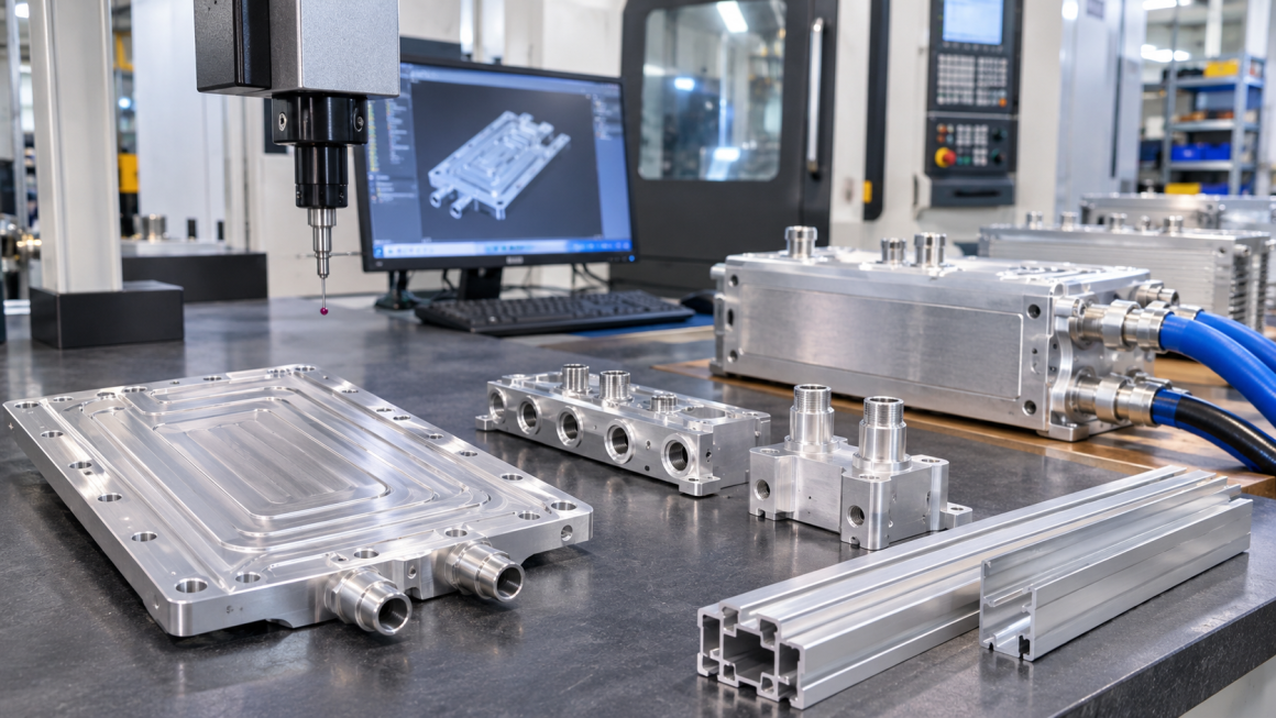
1. Why the Transition from Prototype to Production Matters
AI data center cooling systems are becoming increasingly complex. High-performance processors, dense GPU configurations, and liquid cooling architectures require aluminum components that can meet demanding mechanical, dimensional, thermal, and fluid-handling requirements.
These components may include:
- CNC-machined aluminum cold plates
- Liquid cooling manifolds
- Extruded aluminum cooling channels
- Heat sinks and thermal structures
- Mounting brackets and support frames
- Custom aluminum housings and connection plates
Developing an initial prototype is an important first step, but a successful prototype does not automatically guarantee a manufacturable production component.
A part that can be produced through one-off CNC machining may become too expensive or slow to manufacture in larger quantities. Similarly, a design that performs well in a laboratory test may require additional engineering changes before it can be manufactured consistently.
The transition from AI cooling aluminum hardware prototype to production therefore requires a structured approach.
Three stages are particularly important:
- Prototype: Verify the design, interfaces, dimensions, and initial performance.
- Pilot production: Confirm that the manufacturing process can repeatedly produce acceptable parts.
- Mass production: Establish stable processes, controlled costs, reliable delivery, and consistent quality.
Each stage has different manufacturing priorities and investment requirements.
2. Prototype Manufacturing: Prioritizing Design Verification
The prototype stage is primarily about learning whether the proposed design works.
At this point, the design may still change. Engineers may need to adjust channel geometry, mounting positions, wall thickness, sealing interfaces, or material selection after reviewing the first samples.
Manufacturing flexibility is therefore often more important than unit cost.
2.1 CNC Machining for Early Aluminum Prototypes
CNC machining is frequently suitable for early cooling hardware prototypes because it allows engineers to produce complex geometries without investing in dedicated extrusion or production tooling.
Typical applications include:
- Aluminum cold plate prototypes
- Manifold blocks
- Mounting plates
- Cooling channel samples
- Custom connectors and structural brackets
CNC machining is particularly useful when the design contains complex internal passages, precision interfaces, or features that are difficult to produce through other processes.
However, prototype machining can involve relatively high material removal, long machining cycles, and additional finishing operations.
These costs may be acceptable for a small number of samples but become less attractive when production volumes increase.
2.2 Design Flexibility and Engineering Changes
Prototype designs should allow room for modification.
Common changes include:
- Adjusting coolant inlet and outlet positions
- Revising channel dimensions
- Changing mounting-hole locations
- Modifying sealing grooves
- Increasing local wall thickness
- Improving tool access and machining feasibility
The first prototype should not necessarily be treated as the final production design.
Instead, it should provide measurable feedback for engineering decisions.
2.3 Prototype Testing
Testing at this stage should focus on the most important design assumptions.
Depending on the component, this may include:
- Dimensional inspection
- Surface finish measurement
- Assembly and interface fit checks
- Pressure and leak testing
- Flow distribution evaluation
- Thermal performance testing
- Initial corrosion compatibility assessment
For pressure-containing cooling components, the test method and acceptance criteria should be established according to the design requirements and applicable standards.
The objective is to identify design problems before committing to production tooling or larger manufacturing quantities.
3. Pilot Production: Confirming Manufacturing Repeatability
Pilot production is the bridge between prototype development and mass production.
The purpose is no longer simply to produce a few functional samples. It is to verify that the selected manufacturing process can consistently produce components within the required specifications.
A successful pilot run should provide evidence that the design, equipment, tooling, inspection methods, and production workflow are compatible.
3.1 Moving from Prototype Processes to Production-Oriented Manufacturing
A prototype may be manufactured entirely through CNC machining.
During pilot production, manufacturers should evaluate whether a more efficient process combination is appropriate.
For example:
- Aluminum extrusion for the primary channel or structural profile
- CNC machining for precision interfaces
- Drilling and tapping for connection features
- Welding or brazing where the design and material system permit
- Surface treatment for specified environmental or functional requirements
- Final assembly and inspection
This approach can reduce machining time while preserving precision where it is actually needed.
The appropriate process depends on component geometry, material, volume, performance requirements, and production economics.
3.2 Tooling Investment Decisions
Pilot production is often the stage when manufacturers and customers must decide whether dedicated tooling is justified.
Potential investments include:
- Extrusion dies
- Dedicated machining fixtures
- Inspection gauges
- Assembly fixtures
- Special drilling or cutting tools
- Dedicated testing connections
Tooling should be evaluated against expected production volume, process stability, and future design flexibility.
Investing in a custom extrusion die may reduce material waste and machining time for a recurring profile. However, if the design is still changing significantly, early tooling investment can create unnecessary costs.
A practical approach is to stabilize the major geometry and interface requirements before approving production tooling.
3.3 Pilot Runs Reveal Problems That Prototypes May Miss
A single prototype may be acceptable even when the manufacturing process is not sufficiently stable.
Pilot production can reveal issues such as:
- Variation between machining setups
- Inconsistent wall thickness
- Distortion after machining
- Tool wear affecting dimensions
- Difficult fixture positioning
- Surface treatment variation
- Assembly inconsistencies
- Longer-than-expected cycle times
These problems should be identified and corrected before the production process is released.
3.4 Establishing Process Documentation
Pilot production should generate manufacturing documentation that can be used in subsequent production runs.
Typical documents include:
- Approved engineering drawings
- Bill of materials
- Process flow diagrams
- Machining and assembly instructions
- Inspection plans
- Testing procedures
- Material and process traceability records
- Nonconformance and corrective-action records
This documentation provides the foundation for repeatable production.
4. Mass Production: Optimizing Cost, Quality, and Delivery
Once the design and manufacturing process are sufficiently stable, the project can move toward mass production.
At this stage, the primary objective changes from proving feasibility to delivering consistent products at an economically sustainable cost.
4.1 Manufacturing Process Optimization
Mass production often requires a more integrated manufacturing route.
For aluminum cooling components, this may involve:
- Standardized extrusion profiles
- Dedicated CNC machining fixtures
- Multi-part machining setups
- Optimized cutting strategies
- Automated or semi-automated inspection
- Standardized surface treatment processes
- Controlled assembly workflows
The goal is to reduce unnecessary operations while maintaining the required dimensional and functional performance.
4.2 Reducing Unit Cost Without Compromising Critical Features
Cost optimization should focus on the entire manufacturing process rather than simply reducing the raw material price.
Potential opportunities include:
- Reducing unnecessary machining volume
- Standardizing common hole and thread sizes
- Optimizing extrusion cross-sections
- Combining compatible machining operations
- Improving material utilization
- Reducing repeated handling and setup
- Simplifying inspection where risk-based controls permit
However, cost reduction should not compromise critical dimensions, sealing surfaces, pressure boundaries, or material compatibility.
For liquid cooling hardware, manufacturing cost must be evaluated alongside reliability and validation requirements.
4.3 Production Capacity and Delivery Planning
Mass production requires a more predictable supply chain.
Manufacturers should evaluate:
- Raw material availability
- Extrusion and machining capacity
- Surface treatment capacity
- Testing throughput
- Packaging requirements
- Export and logistics arrangements
- Buffer stock and replenishment planning
The production lead time should reflect the complete manufacturing route rather than only the CNC machining cycle.
For projects with multiple cooling components, delivery schedules should also consider the availability of related parts and assembly dependencies.
5. How Tolerance Requirements Change Across Production Stages
Dimensional tolerance is one of the most important considerations when moving from prototype to production.
However, tighter tolerances are not automatically better.
The correct tolerance should be based on function, assembly requirements, sealing performance, and manufacturing capability.
5.1 Prototype: Confirming Functional Dimensions
During prototyping, engineers should identify which dimensions are critical to the component’s performance.
Examples include:
- Mounting-hole positions
- Manifold connection interfaces
- Sealing groove dimensions
- Flatness of specified contact surfaces
- Channel locations
- Overall assembly dimensions
Other dimensions may allow more flexibility if they do not affect function or integration.
This distinction helps avoid unnecessary machining costs.
5.2 Pilot Production: Confirming Process Capability
During pilot production, manufacturers should determine whether the selected process can repeatedly achieve the specified tolerances.
This may involve:
- Measuring multiple samples
- Comparing dimensions across production batches
- Reviewing machining variation
- Evaluating fixture repeatability
- Monitoring tool wear
- Identifying process-sensitive features
Where appropriate, statistical process control and capability analysis can be introduced for critical characteristics.
5.3 Mass Production: Maintaining Controlled Variation
In mass production, inspection must be supported by stable process controls.
Important practices include:
- Approved production drawings
- Defined measurement methods
- Calibrated inspection equipment
- First-article inspection where required
- In-process inspection
- Final dimensional verification
- Defined reaction plans for nonconforming products
Critical dimensions should be clearly identified rather than assigning unnecessarily tight tolerances to every feature.
6. Testing Requirements: From Initial Validation to Production Control
Testing requirements should evolve as the project progresses.
Prototype testing primarily evaluates the design. Pilot testing evaluates the manufacturing process and repeatability. Production testing confirms that delivered components meet the agreed specifications.
| Testing Area | Prototype | Pilot Production | Mass Production |
|---|---|---|---|
| Dimensional inspection | Verify key design dimensions | Confirm repeatability across samples | Routine inspection of critical features |
| Assembly fit | Confirm interface compatibility | Verify repeated assembly | Controlled assembly checks |
| Pressure testing | Validate the initial design | Confirm process consistency | Defined production acceptance procedure |
| Leak testing | Identify initial leakage risks | Verify manufacturing repeatability | Routine testing according to the control plan |
| Flow testing | Evaluate initial flow behavior | Compare results across samples | Process or batch verification as specified |
| Thermal testing | Validate design assumptions | Confirm representative performance | Periodic or defined verification |
| Material verification | Confirm material selection | Verify material and supplier consistency | Incoming and traceability controls |
6.1 Pressure and Leak Testing
For cold plates and manifolds, pressure and leak testing are important because manufacturing defects can compromise the coolant boundary.
The test procedure should define:
- Test medium
- Test pressure
- Test duration
- Temperature conditions
- Connection and sealing arrangements
- Acceptance criteria
- Inspection and recording requirements
The appropriate method depends on the component design and applicable requirements.
A pressure test and a leak test are not interchangeable. They address related but different aspects of component integrity.
6.2 Flow and Thermal Performance
A prototype may require more extensive flow and thermal characterization to validate the design.
During pilot production, representative samples can be used to determine whether manufacturing variation affects flow distribution or thermal performance.
For mass production, the testing strategy may use a combination of routine checks, periodic verification, and process monitoring.
The testing frequency should reflect component criticality, process stability, customer requirements, and the consequences of failure.
7. Lead Time and Cost Differences Across the Three Stages
The production stage has a direct impact on both delivery time and total project cost.
| Factor | Prototype | Pilot Production | Mass Production |
|---|---|---|---|
| Typical quantity | Small sample quantity | Limited production batch | Recurring or larger volumes |
| Main objective | Design verification | Process validation | Stable delivery |
| Manufacturing | Flexible CNC and manual operations | Mixed processes and dedicated fixtures | Optimized and standardized processes |
| Tooling | Usually limited | Selective investment | Dedicated tooling where justified |
| Unit cost | Usually highest | Intermediate | Potentially lower at sufficient volume |
| Lead-time focus | Fast sample development | Process preparation and batch execution | Capacity and supply-chain planning |
| Design changes | Relatively flexible | Controlled and increasingly restricted | Formal change control |
The actual quantities, lead times, and cost differences depend on the component geometry, supplier capacity, material availability, tooling requirements, and testing scope.
A lower unit price in mass production should not be evaluated without considering tooling amortization, inventory, quality controls, and engineering changes.
8. Engineering Change Management: Avoiding Costly Production Disruptions
One of the most overlooked challenges in aluminum cooling component manufacturing is managing design changes after production preparation has begun.
A small design adjustment can affect tooling, machining programs, inspection fixtures, assembly processes, and previously manufactured inventory.
8.1 Prototype Stage: Record and Evaluate Changes
During prototype development, changes are expected.
Each revision should identify:
- What has changed
- Why the change is necessary
- Which dimensions or functions are affected
- Whether previous test results remain valid
- Whether a new prototype is required
Even at this early stage, revision control helps prevent confusion between different sample configurations.
8.2 Pilot Stage: Freeze Critical Interfaces
Before pilot production, the project should establish a controlled design baseline.
Particular attention should be given to:
- Mounting interfaces
- Coolant inlet and outlet positions
- Sealing features
- Pressure boundary geometry
- Material specifications
- Critical dimensions
- Testing requirements
Changes after pilot production begins should be evaluated for their impact on cost, schedule, tooling, and validation.
8.3 Mass Production: Formal Engineering Change Control
During mass production, changes should follow an agreed approval process.
A typical engineering change process includes:
- Submit a formal change request.
- Review the technical reason and affected requirements.
- Evaluate manufacturing and tooling impacts.
- Assess inventory and work-in-process implications.
- Determine whether additional testing is necessary.
- Approve the revised drawing and production documents.
- Implement the change using a controlled revision.
Suppliers should not independently modify critical dimensions, materials, or manufacturing processes without the required approval.
Likewise, customers should understand that changes to approved specifications may affect cost and delivery schedules.
9. Choosing the Right Manufacturing Route for AI Cooling Aluminum Hardware
Different aluminum cooling components require different manufacturing strategies.
The optimal route depends on geometry, performance requirements, quantity, and expected product lifecycle.
9.1 CNC-Machined Cold Plates and Manifolds
CNC machining is suitable for complex cooling components requiring precision channels, connection interfaces, and sealing features.
A practical development route may be:
- Prototype: CNC machining from billet or plate
- Pilot: Optimize fixtures and machining sequences
- Production: Standardize setups and improve cycle time
For some designs, alternative processes such as extrusion, brazing, or other joining methods may be evaluated where technically appropriate.
9.2 Extruded Aluminum Cooling Profiles
Extrusion can be attractive for components with repeated cross-sectional geometry.
Potential applications include:
- Cooling channels
- Heat sink profiles
- Structural cooling supports
- Manifold housings
- Mounting and thermal interface structures
A typical route may be:
- Prototype: CNC-machined samples or available standard profiles
- Pilot: Custom extrusion die and initial production trials
- Production: Stable extrusion, cutting, machining, and finishing processes
Custom die investment should be considered only after the required profile geometry and material specifications are sufficiently stable.
9.3 Hybrid Extrusion and CNC Manufacturing
Combining extrusion with CNC machining can balance material efficiency and dimensional precision.
Extrusion provides the primary profile geometry, while CNC machining creates precision interfaces, holes, grooves, and connection features.
This approach can be useful for recurring AI cooling hardware designs where a fully machined billet would create excessive material waste or processing time.
The design should account for extrusion tolerances, machining allowances, distortion, and the relationship between extruded and machined surfaces.
10. A Practical Prototype-to-Production Roadmap
A structured transition helps reduce unnecessary tooling investment and production risk.
Step 1: Define the Application Requirements
Confirm the component’s function, installation environment, material requirements, coolant conditions, pressure requirements where applicable, and critical interfaces.
Step 2: Develop and Manufacture the Prototype
Select a flexible manufacturing route to produce initial samples and verify the design.
Step 3: Complete Design Validation
Review dimensional, mechanical, thermal, fluid, and assembly performance according to the component’s intended function.
Step 4: Review Design for Manufacturability
Identify unnecessary machining operations, difficult geometries, tolerance conflicts, and potential opportunities for extrusion or process integration.
Step 5: Establish the Pilot Production Plan
Define quantities, tooling requirements, fixtures, inspection methods, testing procedures, and acceptance criteria.
Step 6: Complete Pilot Production and Process Review
Evaluate sample consistency, process stability, yield, production time, and manufacturing cost.
Step 7: Approve the Production Baseline
Release controlled drawings, material specifications, process documents, and quality requirements.
Step 8: Scale Production with Ongoing Quality Monitoring
Monitor critical dimensions, process variation, supplier performance, delivery consistency, and customer feedback.
11. How to Select an Aluminum Manufacturing Partner for AI Cooling Projects
A suitable manufacturing partner should be able to support more than the production of a single prototype.
The supplier should understand how design decisions affect manufacturability, quality, cost, and production scalability.
Important evaluation criteria include:
- Experience with aluminum extrusion and CNC machining
- Ability to manufacture complex cooling geometries
- Understanding of sealing and pressure-boundary requirements
- Dimensional inspection capability
- Appropriate pressure and leak testing facilities
- Material and process traceability
- Tooling and fixture development experience
- Pilot production support
- Stable production capacity
- Engineering change management procedures
It is also important to clarify the division of responsibilities.
The customer or system integrator should define application requirements and acceptance criteria. The manufacturer should confirm process feasibility, manufacturing capability, inspection methods, and production risks.
For development projects, technical specifications, drawings, testing scope, tooling ownership, and change approval procedures should be agreed upon before production commitments are made.
12. Conclusion: Scale Manufacturing Only After the Process Is Ready
Moving AI cooling aluminum hardware from prototype to production requires more than increasing manufacturing quantities.
Each stage serves a different purpose.
Prototypes help verify the design. Pilot production confirms manufacturing repeatability. Mass production establishes cost efficiency, process control, and reliable delivery.
The most effective transition strategy is to preserve flexibility during early development, invest selectively in tooling during pilot production, and standardize the manufacturing process before scaling.
For AI cooling components, particular attention should be given to critical dimensions, coolant boundaries, sealing interfaces, material compatibility, and testing requirements.
By aligning engineering design with manufacturing capability from the beginning, project teams can reduce unnecessary rework, avoid premature tooling investment, and establish a more reliable route to commercial production.
A successful prototype proves that a component can work. A successful production process proves that it can be manufactured consistently, economically, and repeatedly.