1. Why Existing AI Racks Are Being Considered for Liquid Cooling Retrofits
As AI workloads become more computationally intensive, conventional air-cooled data center infrastructure may no longer provide sufficient thermal management for some high-density GPU deployments.
Liquid cooling offers a practical approach to removing heat closer to the processors. However, introducing liquid cooling into an existing data center does not always require replacing every rack.
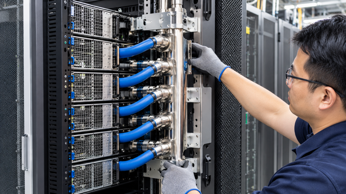
In some facilities, existing rack structures can be adapted through carefully designed mechanical modifications, additional support brackets, cooling manifolds, hose management systems, and revised cable-routing arrangements.
Retrofitting existing AI racks for liquid cooling can help reduce replacement costs, preserve existing infrastructure, and shorten upgrade schedules.
However, a successful retrofit is not simply a matter of installing a cooling manifold or adding a few aluminum brackets. The existing rack must be evaluated as part of a complete mechanical, thermal, electrical, and maintenance system.
The central engineering question is:
Can the existing rack safely and reliably accommodate the new cooling architecture without compromising structural integrity, serviceability, or operational safety?
2. Assessing the Load-Bearing Capacity of Existing Racks
Structural capacity should be the first consideration before any physical modification begins.
Liquid cooling can introduce additional loads that were not considered in the original air-cooled rack design.
These may include:
- Additional cooling manifolds and distribution hardware
- Coolant-filled hoses and associated fittings
- Pump or coolant distribution components, where rack-mounted
- Additional support brackets and reinforcement members
- Changes in server weight resulting from liquid-cooled hardware
- Dynamic loads caused by equipment operation, maintenance, or vibration
2.1 Review the Original Rack Specifications
The first step is to collect the available structural information:
- Maximum rated static load
- Permitted dynamic loading, if specified
- Vertical post and crossmember dimensions
- Frame material and wall thickness
- Joint and fastener configurations
- Existing equipment weight distribution
- Floor anchoring and seismic requirements, where applicable
A rack’s published load rating should not automatically be interpreted as available capacity for additional cooling equipment.
The actual remaining capacity depends on the installed equipment, load distribution, support conditions, and the way new components transfer their loads into the frame.
2.2 Identify Localized Load Concentrations
A cooling manifold mounted on one side of a rack may introduce concentrated loads rather than evenly distributed loading.
Similarly, a heavy cooling module installed at the rear of a rack may change its center of gravity.
Engineers should examine:
- Local bending of mounting rails
- Deflection of horizontal crossmembers
- Load transfer through vertical posts
- Fastener pull-out or joint deformation
- Rack stability under asymmetric loading
- Floor loading and anchoring conditions
A rack that can support the total weight may still experience unacceptable local deformation.
2.3 When Reinforcement Is Necessary
If the existing structure has sufficient overall capacity but lacks suitable mounting points or local stiffness, reinforcement may be possible.
Typical solutions include:
- Additional aluminum crossmembers
- Reinforced mounting plates
- Modular side brackets
- Rear support frames
- Load-distribution plates
- Additional fastening points
The reinforcement should transfer loads into appropriate structural members rather than relying on thin enclosure panels or unsupported sheet-metal sections.
3. Evaluating Installation Space and Component Compatibility
Physical space is often one of the most difficult constraints in an AI rack liquid cooling retrofit.
An existing rack may have been designed around air-cooled servers, with limited provisions for rear-mounted manifolds, coolant distribution hardware, and additional hose connections.
Liquid cooling introduces new spatial requirements that must be considered together.
3.1 Check Front-to-Rear Installation Depth
Engineers should review the available depth for:
- Existing server chassis
- Liquid-cooled server configurations
- Rear-mounted manifolds
- Quick-disconnect fittings
- Hose connections and bending space
- Cable connectors and power distribution equipment
- Rear doors and service access
A cooling component may physically fit inside the rack but still prevent the rear door from closing or obstruct server removal.
3.2 Review Vertical and Side-Mounting Space
Potential installation positions include:
- Rear vertical mounting rails
- Side-mounted manifold supports
- Additional horizontal crossmembers
- Dedicated equipment mounting zones
- External rack-side cooling assemblies
The most suitable arrangement depends on the rack’s original architecture and the cooling system’s connection requirements.
Modular cooling brackets can provide additional mounting flexibility without requiring extensive modification to the original rack frame.
3.3 Avoid Interference with Existing Infrastructure
A retrofit assessment should identify potential conflicts between cooling hardware and:
- Power distribution units
- Busbar support structures
- Cable trays
- Network cables
- Grounding and bonding connections
- Existing ventilation paths
- Door mechanisms and removable panels
Aluminum structural components can provide useful mounting flexibility, but electrical insulation, protective bonding, and clearance requirements must be evaluated independently.
4. Designing Coolant Routing for Existing Rack Layouts
Coolant routing is not simply a matter of finding an available path for hoses.
The routing arrangement affects installation, pressure drop, mechanical loading, leak exposure, and future maintenance.
4.1 Establish Supply and Return Paths
Before installing new components, engineers should map the complete coolant flow path:
- Facility or row-level coolant distribution connection
- Rack-level supply connection
- Manifold inlet
- Server or cooling-module connections
- Return manifold
- Rack-level return connection
The actual arrangement depends on the cooling architecture, including direct-to-chip liquid cooling and other liquid-cooled configurations.
Supply and return lines should be clearly identified and arranged to reduce the risk of incorrect connection during installation or maintenance.
4.2 Manage Hose Bending and Mechanical Loads
Existing racks may not have been designed to accommodate flexible coolant hoses.
A retrofit should therefore evaluate:
- Minimum bend radius specified by the hose manufacturer
- Hose length and movement allowance
- Connection accessibility
- Support points and routing clips
- Potential contact with sharp edges
- Interference during server insertion and removal
- Loads transferred to quick-disconnect fittings
Hoses should not be allowed to hang unsupported from manifold connections.
Where appropriate, separate hose supports should carry hose weight and reduce bending or axial forces transferred to fittings.
4.3 Consider Quick-Disconnect Accessibility
Quick-disconnect (QD) fittings can simplify server replacement and cooling-module maintenance.
However, their usefulness depends on installation position and service access.
A good retrofit design should allow technicians to:
- Identify the correct connection
- Reach the fitting without removing unrelated equipment
- Disconnect it using the specified procedure
- Avoid twisting or overloading connected hoses
- Reconnect it without forcing alignment
QD selection must also consider coolant compatibility, operating pressure, flow requirements, and the manufacturer’s connection and disconnection procedures.
5. Modular Cooling Brackets: A Practical Retrofit Strategy
Modular cooling brackets are particularly useful when an existing rack is structurally sound but lacks dedicated mounting interfaces for liquid cooling equipment.
Rather than redesigning the entire rack, engineers can introduce additional mounting structures that adapt the original frame to the new cooling arrangement.
5.1 Side-Mounting Brackets
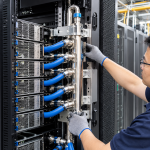
Side-mounted brackets can support vertical manifolds, hose guides, and selected cooling accessories.
Their advantages include:
- Making use of otherwise unused side space
- Reducing interference with server installation
- Allowing different bracket lengths and positions
- Simplifying replacement of individual components
The design must account for the available side clearance and the load capacity of the attachment points.
5.2 Rear-Mounting Support Brackets
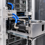
Rear-mounted brackets can provide support for manifolds, distribution hardware, and hose-management components.
They should be designed around:
- Manifold dimensions
- Fitting orientation
- Hose connection space
- Rear door clearance
- Equipment extraction paths
- Required maintenance access
5.3 Adjustable Aluminum Mounting Systems
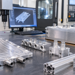
Custom aluminum extrusions and CNC-machined brackets can provide adaptable mounting interfaces.
Potential features include:
- Slotted mounting holes
- Adjustable crossmembers
- Replaceable connection plates
- Standardized fastening interfaces
- Multiple mounting positions
- Corrosion-resistant surface treatments
The main advantage is modularity: individual cooling components can be repositioned or replaced without rebuilding the entire rack.
However, modularity does not remove the need for structural verification. Bracket stiffness, fastener strength, local frame loading, and vibration resistance must still be evaluated.
6. Maintaining Service Clearance After the Retrofit
A liquid cooling retrofit should not make an existing rack more difficult to maintain.
In fact, maintenance access becomes even more important because cooling connections introduce additional components and potential service operations.
Engineers should consider the complete maintenance sequence:
Isolation → Access → Disconnection → Component Removal → Replacement → Reconnection → Verification
6.1 Server Extraction Space
Cooling hoses and manifold connections should not block the removal path of servers.
The design should consider whether a server can be withdrawn without:
- Removing unrelated cooling equipment
- Disturbing neighboring hoses
- Disconnecting unnecessary electrical cables
- Applying excessive force to QD fittings
6.2 Manifold and Hose Access
Manifolds should be positioned where technicians can inspect connections and perform maintenance.
Important considerations include:
- Visibility of fittings and connection points
- Access to isolation valves
- Space for tools
- Hose identification
- Leak inspection access
- Replacement clearance
6.3 Avoid Creating New Maintenance Dependencies
A poorly planned retrofit can create situations where one component must be removed before another can be serviced.
For example, a rear manifold installed directly behind a cable management assembly may require the cable assembly to be removed before a leaking connection can be accessed.
These dependencies should be identified during the design stage rather than discovered during operation.
7. Validation Requirements Before Returning the Rack to Service
A retrofit should be treated as an engineering modification, not simply an installation activity.
The modified rack requires appropriate validation before it returns to operation.
7.1 Structural Verification
Depending on the scope of modification, validation may include:
- Review of updated structural calculations
- Inspection of mounting interfaces
- Static load testing
- Deflection measurement
- Fastener and joint inspection
- Stability assessment
- Vibration assessment where relevant
Testing loads and acceptance criteria should be established according to the rack design, applicable standards, and project requirements.
7.2 Coolant-System Validation
The cooling system should be evaluated separately from the rack’s mechanical structure.
Typical checks include:
- Connection compatibility
- Coolant-side material compatibility
- Pressure testing
- Leak testing
- Flow verification
- Pressure-drop evaluation
- Functional checks of isolation components
Pressure and leak testing procedures must follow the design requirements and the specifications of the cooling-system components.
7.3 Electrical and Operational Verification
Liquid cooling introduces additional interfaces with existing electrical infrastructure.
The retrofit should therefore include checks for:
- Electrical clearances
- Insulation barriers
- Protective bonding and grounding
- Cable routing and retention
- Power distribution access
- Equipment service procedures
The aluminum rack frame should not automatically be treated as a current-carrying busbar or as a verified protective grounding conductor.
7.4 Integrated System Testing
Individual component tests are not enough to establish that the modified rack is ready for operation.
Integrated testing should examine:
- Mechanical stability under representative operating conditions
- Coolant flow and temperature behavior
- Leakage under the specified operating conditions
- Hose movement and connection stability
- Equipment access and replacement procedures
- Monitoring and alarm functions, where applicable
The final acceptance criteria should be documented and agreed upon before the retrofit begins.
8. Partial Retrofit vs. Complete Rack Replacement
Not every existing rack is a suitable candidate for liquid cooling conversion.
The decision should be based on structural condition, available space, cooling architecture, modification complexity, and long-term operational requirements.
| Evaluation Factor | Partial Retrofit | Complete Replacement |
|---|---|---|
| Structural condition | Existing frame remains suitable | Frame is damaged, inadequate, or unsuitable |
| Load capacity | Sufficient capacity with limited reinforcement | Required loads exceed practical reinforcement limits |
| Installation space | Sufficient space for cooling components | Major space conflicts cannot be resolved |
| Coolant routing | Practical hose and manifold paths available | Existing layout prevents reliable routing |
| Maintenance access | Service clearance can be preserved | Access remains inadequate after modification |
| Project cost | Modification cost is lower | Extensive modification approaches replacement cost |
| Future expansion | Existing structure supports planned upgrades | New architecture requires a different rack design |
8.1 When Partial Retrofit Makes Sense
Partial retrofit is generally worth considering when:
- The existing rack is structurally sound
- The installed equipment remains compatible
- Additional mounting points can be introduced
- Coolant routing can be achieved without major interference
- Maintenance access can be preserved
- Required validation can be completed
In these cases, modular brackets, additional crossmembers, and dedicated hose-management hardware may provide a cost-effective upgrade path.
8.2 When Complete Replacement Is More Practical
Complete replacement may be more appropriate when:
- The existing rack has insufficient structural capacity
- Its dimensions cannot accommodate the new cooling architecture
- The frame has significant damage or deformation
- Major structural modifications would be necessary
- Electrical and cooling infrastructure cannot be integrated safely
- Future expansion requires a substantially different rack configuration
The decision should not be based on the initial purchase price alone.
The total cost of ownership should include engineering, modification, installation downtime, testing, maintenance, and future upgrade requirements.
9. A Practical Workflow for an AI Rack Liquid Cooling Retrofit Project
A structured workflow can reduce engineering uncertainty and prevent unnecessary modifications.
Step 1: Existing Rack Survey
Collect rack drawings, dimensions, material information, load ratings, and photographs of the installed configuration.
Step 2: Cooling Architecture Review
Confirm the server cooling configuration, manifold requirements, coolant connections, hose specifications, and external distribution interfaces.
Step 3: Mechanical Compatibility Assessment
Evaluate structural capacity, mounting locations, available space, and potential interference with existing equipment.
Step 4: Retrofit Concept Design
Develop bracket layouts, reinforcement concepts, manifold positions, hose routing, and maintenance access arrangements.
Step 5: Prototype and Fit Check
Install representative components or a prototype bracket system to verify dimensions, connection access, and equipment extraction paths.
Step 6: Engineering Validation
Complete the required structural, coolant-side, electrical, and functional verification.
Step 7: Controlled Installation and Commissioning
Implement the approved modification, document the installation, and complete the agreed acceptance checks before returning the rack to service.
10. How Aluminum Components Support Liquid Cooling Rack Upgrades
Aluminum components can play an important role in adapting existing data center racks.
Custom extrusions, CNC-machined mounting plates, and modular brackets can provide additional interfaces for cooling equipment without requiring complete replacement of the original structure.
Potential applications include:
- Adjustable manifold support brackets
- Rear-mounted cooling equipment frames
- Side-mounted hose management structures
- Reinforced crossmembers
- Removable equipment mounting plates
- Modular service-access assemblies
For retrofit projects, dimensional compatibility is particularly important.
The manufacturer should be able to work from existing rack drawings, physical samples, or verified measurements to develop components that fit the original structure.
Depending on the application, engineering considerations may include alloy selection, wall thickness, machining tolerances, fastening methods, surface treatment, and corrosion compatibility with the surrounding environment.
For coolant-wetted aluminum components, material selection and surface treatment must also be evaluated against the actual coolant chemistry and the complete system’s material combination.
11. Retrofit Decisions Should Start with Engineering Compatibility
Retrofitting existing AI racks for liquid cooling can provide a practical alternative to replacing entire rack systems.
However, the feasibility of an upgrade depends on more than the availability of mounting space.
Structural capacity, load distribution, manifold positioning, coolant routing, hose support, maintenance clearance, electrical integration, and system validation must all be considered together.
Modular cooling brackets and custom aluminum support structures can make partial upgrades more flexible, particularly when the original rack remains mechanically suitable.
When the existing structure cannot meet the new requirements without extensive modification, complete replacement may be the more reliable long-term decision.
The most effective retrofit strategy is therefore not to modify every rack, but to identify which existing structures can be upgraded safely, economically, and maintainably.
For AI data center operators and equipment integrators, a well-designed retrofit begins with a detailed assessment of the existing rack and ends with verified system-level performance.