1.
As AI data centers deploy increasingly powerful GPU servers and liquid cooling systems, equipment maintenance is becoming an important part of infrastructure design.
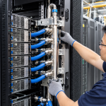
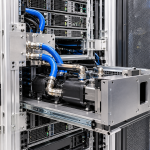
AI racks contain multiple interconnected subsystems, including server modules, power distribution equipment, cooling manifolds, pumps, coolant hoses, cold plates, sensors, and electrical connections.
When a component requires inspection, replacement, or repair, the maintenance process can become complicated if the surrounding structure does not provide sufficient access.
A cooling module may be technically replaceable, for example, but its removal may require disconnecting several unrelated components. A pump may be accessible from the front, but its mounting bolts may be blocked by cable trays or adjacent structural members.
These problems increase maintenance time and introduce additional risks during disassembly and reassembly.
This is why repairable aluminum AI infrastructure design should be considered from the beginning of the engineering process.
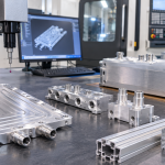
Aluminum extrusions, CNC-machined brackets, modular mounting plates, and removable structural panels can provide flexible mechanical solutions for service-friendly AI infrastructure.
However, modularity alone does not guarantee maintainability.
The complete maintenance sequence must be translated into structural requirements:
- Isolate the equipment safely.
- Access the component.
- Disconnect and remove it.
- Install the replacement.
- Reconnect mechanical, electrical, and fluid interfaces.
- Perform functional verification.
This article explores how aluminum rack structures can support these steps and make AI infrastructure easier to maintain.
2. Design Around the Maintenance Workflow
Traditional rack design often focuses on equipment dimensions, structural loading, thermal management, and installation efficiency.
For service-oriented infrastructure, another question should be considered:
Can a technician replace the required component without unnecessarily dismantling the surrounding system?
The answer depends on how the rack structure supports the actual maintenance workflow.
2.1 Identify Replaceable Components
The first step is to identify which components may require routine inspection, replacement, or repair.
Typical examples include:
- GPU server modules
- Power supply units
- Rack-mounted PDUs
- Cooling pumps
- Coolant distribution modules
- Liquid cooling manifolds
- Quick-disconnect fittings
- Coolant hoses
- Sensors and monitoring devices
- Fans and auxiliary cooling equipment
Not every component requires the same maintenance strategy.
Frequently replaced components should generally have simpler access and removal procedures than components intended to remain installed throughout the rack’s service life.
2.2 Define the Removal Sequence
For each replaceable component, engineers should document its removal sequence.
For example, replacing a coolant distribution module may require:
- Isolating the relevant power supply
- Following the approved coolant isolation procedure
- Accessing the module mounting points
- Disconnecting designated fluid connections
- Disconnecting electrical and monitoring interfaces
- Removing mechanical fasteners
- Extracting the module
- Installing the replacement
- Reconnecting the interfaces
- Performing leak and functional checks
This sequence reveals where the rack design may create unnecessary maintenance difficulties.
If a technician must remove unrelated cable trays, structural members, or adjacent equipment before reaching the target module, the mounting arrangement may need to be redesigned.
2.3 Establish Service Zones
A service zone is a designated area around a component that allows inspection, disconnection, removal, and replacement.
The rack design should account for:
- Tool access
- Fastener removal space
- Connector clearance
- Module extraction direction
- Hose movement
- Cable handling
- Technician access
- Temporary placement of removed components
These requirements should be considered in the three-dimensional rack layout, not added after the mechanical design is complete.
3. Structural Isolation: Making Components Serviceable Without Unnecessary Disassembly
Isolation is the first stage of maintenance.
In AI infrastructure, it involves more than switching off a component. Electrical, mechanical, and fluid interfaces must be managed according to the approved service procedure.
3.1 Electrical Isolation
Power distribution structures should allow maintenance personnel to access the designated isolation devices and electrical connections.
Mechanical design considerations include:
- Access to disconnect switches
- Removable protective covers
- Clear access to electrical connectors
- Adequate space for authorized service tools
- Separation between electrical and coolant service areas
- Clearly identifiable mounting and access interfaces
The rack structure should not obstruct the isolation procedures specified by the equipment manufacturer.
Electrical isolation and verification must be performed by qualified personnel following the applicable safety procedures.
3.2 Coolant Isolation
Liquid-cooled equipment introduces additional service requirements.
Before a cooling component is removed, the relevant coolant circuit may need to be isolated, depressurized, drained, or otherwise prepared according to the system design.
Structural provisions may include:
- Access to isolation valves
- Space around quick-disconnect fittings
- Drain and service port access
- Hose support that allows controlled disconnection
- Removable panels near service interfaces
- Protection against accidental contact with adjacent components
The exact procedure depends on the coolant distribution architecture.
A modular rack should make these service points accessible without requiring extensive removal of unrelated hardware.
3.3 Independent Service Interfaces
Where practical, electrical, mechanical, and fluid connections should be arranged so that one maintenance task does not unnecessarily disturb other systems.
For example, a replaceable pump assembly should ideally have clearly defined mounting points and service connections.
Its removal should not require dismantling the main structural frame or disturbing neighboring server modules.
4. Access Design: Making Critical Components Easy to Reach
Access is one of the most important factors affecting maintenance time.
A component may be removable in theory but difficult to service if the surrounding rack structure restricts tool movement or extraction space.
4.1 Front, Rear, and Side Access
Different components may require different service directions.
Examples include:
- Server modules removed from the front
- Vertical PDUs accessed from the rear
- Manifolds serviced from the side
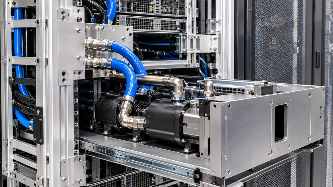
- Pump assemblies removed from dedicated equipment compartments
- Hose connections accessed through removable panels
The rack structure should provide sufficient clearance in the intended service direction.
Engineers should consider the complete extraction path, including the dimensions of the component after it has been disconnected from its mounting interface.
4.2 Tool Access and Fastener Positioning
Fasteners positioned too close to adjacent equipment can make maintenance difficult.
Important design considerations include:
- Wrench and screwdriver clearance
- Fastener head accessibility
- Nut and bolt removal space
- Visibility of mounting points
- Avoidance of hidden or obstructed connections
- Consistent fastener orientation
Where possible, standardized fastener sizes and accessible mounting locations can simplify maintenance operations.
4.3 Removable Panels and Covers
Removable aluminum panels can provide access to internal cooling and electrical components.
Possible solutions include:
- Bolted access panels
- Hinged protective covers
- Sliding panels
- Removable equipment guards
- Modular side plates
The panel design should balance access convenience with structural rigidity, protection, and safety requirements.
A removable panel should not compromise the rack’s required structural performance when installed.
4.4 Service Clearance for Module Extraction
Equipment dimensions alone do not determine whether a module can be replaced.
The rack should provide sufficient space for the complete removal operation.
This includes:
- Connector disconnection
- Fastener removal
- Initial movement away from mounting points
- Extraction from the rack
- Handling and temporary support
- Installation of the replacement unit
The required clearance should be established using actual component dimensions and the intended maintenance procedure.
5. Modular Aluminum Rack Structures
Modularity allows individual sections of a rack to be replaced or reconfigured without rebuilding the complete structure.
Aluminum extrusion systems are particularly useful because their mounting channels and connection features can support flexible mechanical layouts.
5.1 Modular Structural Frames
A modular aluminum rack may consist of:
- Vertical structural profiles
- Horizontal cross-members
- Removable equipment mounting rails
- Reinforced corner connectors
- Modular support brackets
- Replaceable access panels
These elements can be assembled into a common structural platform with dedicated interfaces for different equipment configurations.
5.2 Standardized Mounting Interfaces
Standardized mounting interfaces make replacement and reconfiguration more predictable.
For example, several generations of cooling modules may use a common mounting envelope even when their internal designs differ.
The rack can then accommodate equipment changes through replaceable adapter plates rather than requiring a complete structural redesign.
Important considerations include:
- Mounting-hole patterns
- Datum surfaces
- Positioning features
- Fastener specifications
- Load-bearing capacity
- Alignment tolerances
- Interface revision control
5.3 Replaceable Brackets and Support Members
Not every structural component needs to be permanently integrated.
Some brackets and support members can be designed as replaceable subassemblies.
Examples include:
- Pump mounting plates
- Manifold brackets
- Cable support rails
- Hose retention brackets
- Sensor mounting plates
- Equipment adapter plates
This approach can reduce repair complexity when a local component becomes damaged or requires modification.
However, removable structural connections must retain the required load capacity and stiffness after repeated assembly.
5.4 Avoiding Excessive Modularity
More removable parts do not automatically produce better maintainability.
Every additional joint introduces potential issues involving:
- Fastener loosening
- Alignment variation
- Tolerance accumulation
- Local deformation
- Assembly errors
- Inspection requirements
The objective is to create useful service modules, not to divide the entire rack into unnecessary small components.
6. Replaceable Cooling Modules and Fluid Connections
Liquid cooling is one of the most important areas where service-friendly design can improve infrastructure reliability.
Cooling components may require replacement because of pump failure, connector damage, seal degradation, contamination, or planned equipment upgrades.
6.1 Modular Cooling Assemblies
A cooling module may combine several components into one serviceable assembly.
Depending on the system architecture, this could include:
- Pump assemblies
- Coolant manifolds
- Valves
- Sensors
- Filters
- Internal piping
- Mounting brackets
Combining related components into a removable assembly can simplify maintenance.
However, the module should have clearly defined mechanical, electrical, and fluid interfaces.
6.2 Quick-Disconnect Integration
Quick-disconnect fittings can simplify coolant circuit maintenance by allowing designated connections to be disconnected without conventional pipe dismantling.
Their integration into the aluminum structure requires careful planning.
Consider:
- Connector insertion and removal clearance
- Axial and bending loads
- Hose routing
- Connector alignment
- Retention mechanisms
- Coolant compatibility
- Pressure and temperature ratings
- Drip-management requirements
The rack should provide enough mechanical support to prevent hose weight or installation forces from being transferred unnecessarily to the fittings.
Quick-disconnects must be selected and operated according to their specifications and the system’s isolation procedure.
6.3 Hose Routing for Replacement
Hose routing should support both normal operation and maintenance.
An arrangement that works well during initial installation may become difficult to service if hoses are tightly packed around other equipment.
The design should allow:
- Connector access
- Controlled hose movement
- Appropriate bend radius
- Removal without excessive twisting
- Separation from sharp structural edges
- Replacement without dismantling unrelated components
Dedicated aluminum or polymer hose guides can help maintain consistent routing while providing sufficient flexibility for service operations.
6.4 Manifold and Pump Mounting
Cooling manifolds and pump assemblies should be mounted through accessible mechanical interfaces.
For example, a manifold may be installed on a removable CNC-machined aluminum mounting plate.
The plate can then be removed as part of a service procedure, provided that the associated fluid connections and system isolation requirements have been addressed.
This can simplify replacement compared with mounting each component directly onto permanent rack members.
7. Reconnection: Designing for Repeatable Assembly
Removing a component is only half of the maintenance process.
After replacement, electrical, mechanical, and fluid interfaces must be reconnected correctly.
Poor interface design can lead to alignment problems, damaged seals, incorrect fastener installation, or inconsistent assembly quality.
7.1 Mechanical Positioning Features
Positioning features can help ensure that replacement modules are installed consistently.
Examples include:
- Locating pins
- Machined datum surfaces
- Guide rails
- Alignment slots
- Mechanical stops
- Defined mounting references
These features reduce dependence on manual positioning and can help prevent incorrect installation.
7.2 Fastener Standardization
Where practical, standardized fasteners can simplify replacement operations.
The design should consider:
- Fastener size and type
- Required tightening procedure
- Thread engagement
- Access direction
- Repeated assembly
- Material compatibility
For aluminum threaded interfaces, repeated disassembly may affect thread durability.
Depending on the application, engineers may consider replaceable threaded inserts or through-bolt arrangements.
7.3 Sealing Interface Repeatability
Fluid connections require particular attention during reassembly.
O-rings, gaskets, and sealing surfaces should be protected against damage during removal and installation.
The service procedure should define which sealing elements must be replaced and how mating surfaces should be inspected.
The mechanical design should provide sufficient access to allow proper inspection and assembly without forcing technicians to work at awkward angles.
7.4 Electrical and Sensor Connections
Electrical connectors and monitoring interfaces should be accessible and identifiable.
Where possible, connectors should be arranged to reduce the risk of accidental damage during module removal.
Cable length and routing should allow the required disconnection movement without creating excessive tension or interference.
Electrical reconnection should follow the equipment manufacturer’s specifications and applicable safety procedures.
8. Functional Testing After Replacement
A replacement component should not be considered operational simply because it has been mechanically installed.
The complete maintenance sequence should include verification of the affected systems.
8.1 Mechanical Inspection
After installation, inspect:
- Mounting alignment
- Fastener installation
- Bracket condition
- Structural connections
- Cable and hose routing
- Connector retention
- Clearance from adjacent equipment
8.2 Coolant Circuit Verification
For cooling components, the required verification may include:
- Inspection of fluid connections
- Appropriate pressure testing
- Leak testing
- Coolant circulation verification
- Flow or differential pressure checks
- Sensor readings
- Temperature monitoring
The exact tests depend on the replaced component and the system’s maintenance procedure.
8.3 Electrical and Control Verification
Where electrical components are replaced, verification may include:
- Connection inspection
- Protective bonding checks where applicable
- Power-up procedure
- Electrical measurements
- Communication checks
- Alarm and monitoring verification
8.4 System-Level Functional Testing
After individual component checks, the affected subsystem should be evaluated under representative operating conditions.
For example, replacing a pump may require confirmation of circulation, flow stability, operating temperature, and relevant monitoring signals.
Replacing a manifold may require verification that the intended cooling circuits are connected correctly and that no leakage or abnormal pressure behavior is present.
Testing should follow the approved commissioning or maintenance procedure.
9. Aluminum Manufacturing Solutions for Service-Friendly AI Infrastructure
Manufacturing processes influence how easily modular components can be produced, assembled, and replaced.
9.1 Custom Aluminum Extrusions
Custom extrusions can integrate structural and service-related features into a single profile.
Potential applications include:
- Modular rack frames
- Removable mounting rails
- Equipment support channels
- Cable and hose management profiles
- Adjustable bracket interfaces
- Access panel mounting structures
Integrated slots and channels can simplify the installation of replaceable brackets and equipment supports.
9.2 CNC-Machined Mounting Components
CNC machining is useful for producing precision interfaces for replaceable modules.
Typical applications include:
- Pump mounting plates
- Cooling manifold brackets
- Adapter plates
- Alignment blocks
- Reinforced connectors
- Removable equipment supports
Precision machining can help maintain repeatable positioning between replacement modules and the main rack structure.
9.3 Sheet Aluminum Panels and Covers
Fabricated aluminum panels can be used for removable service covers and protective enclosures.
Depending on the application, these may include:
- Hinged access panels
- Removable side covers
- Cooling module guards
- Cable protection panels
- Equipment separation plates
The design should consider structural function, access requirements, edge protection, and surface treatment.
9.4 Surface Treatment and Maintenance
Surface treatment should be selected according to corrosion resistance, wear, appearance, and the intended operating environment.
For components that are frequently assembled or disassembled, contact surfaces and threaded interfaces deserve additional attention.
The finish should not interfere with dimensional fit, grounding interfaces, or mechanical positioning features.
10. Quality Control and Maintainability Validation
Maintainability should be validated as part of the product development process.
A rack may meet its structural requirements but still perform poorly during actual maintenance operations.
A practical validation plan should include:
| Validation area | Key evaluation points |
|---|---|
| Module accessibility | Tool access, connector visibility, extraction clearance |
| Removal procedure | Disconnection sequence and component handling |
| Mounting repeatability | Positioning, alignment, fastener consistency |
| Fluid connections | Hose routing, seal condition, leakage verification |
| Electrical interfaces | Connector access and required safety checks |
| Structural integrity | Load capacity before and after repeated assembly |
| Serviceability | Time, steps, and tools required for replacement |
| Functional verification | Cooling, electrical, and monitoring performance |
10.1 Repeated Assembly and Disassembly Testing
For frequently serviced interfaces, repeated assembly testing can help identify problems such as:
- Thread wear
- Fastener damage
- Bracket deformation
- Alignment changes
- Seal damage
- Connector retention problems
The number of cycles and acceptance criteria should be based on expected maintenance frequency and project requirements.
10.2 Maintenance Simulation
A practical maintenance simulation should use the actual equipment configuration or a representative prototype.
The process can record:
- Number of removal steps
- Tools required
- Components that must be temporarily removed
- Access limitations
- Replacement time
- Reassembly issues
- Post-maintenance test results
This provides useful feedback for improving the structural design before production.
10.3 Documentation and Revision Control
Replaceable modules should have clearly defined mechanical interfaces and revision-controlled documentation.
Relevant records may include:
- Assembly drawings
- Exploded views
- Part numbers
- Mounting specifications
- Fastener requirements
- Hose and connector configurations
- Replacement instructions
- Inspection and functional test procedures
Consistent documentation helps ensure that replacement components remain compatible with the original infrastructure.
11. Practical Design Checklist: From Isolation to Functional Testing
The following checklist translates the maintenance workflow into engineering requirements.
Stage 1: Isolation
- Provide access to designated electrical isolation points.
- Identify coolant isolation and service connections.
- Allow safe access to relevant components and covers.
- Avoid requiring unnecessary removal of unrelated equipment.
Stage 2: Access
- Define service zones around replaceable modules.
- Provide sufficient tool and hand clearance.
- Ensure that connector positions are accessible.
- Confirm the complete extraction path.
Stage 3: Disassembly
- Use accessible and standardized fasteners where practical.
- Design removable mounting plates and brackets.
- Protect fluid and electrical interfaces during removal.
- Avoid disturbing permanent structural members unnecessarily.
Stage 4: Replacement
- Provide standardized mechanical interfaces.
- Include positioning and alignment features.
- Confirm that replacement modules fit the defined mounting envelope.
- Support the module during installation.
Stage 5: Reconnection
- Allow correct hose and cable routing.
- Protect sealing interfaces.
- Maintain connector alignment.
- Define fastener and assembly requirements.
Stage 6: Functional Testing
- Inspect mechanical connections.
- Perform required coolant pressure and leak checks.
- Verify electrical and control interfaces.
- Confirm normal operation of the affected subsystem.
The purpose is to make maintenance a predictable engineering process rather than an improvised response to equipment failure.
12.
Fast replacement and repair are important considerations in the design of modern AI infrastructure.
As liquid cooling, power distribution, and high-density computing systems become more integrated, maintenance operations can become increasingly complicated unless the rack structure is designed to support them.
Repairable aluminum AI infrastructure should provide more than modular components. It should support the complete maintenance sequence, from isolation and access to removal, replacement, reconnection, and functional verification.
Custom aluminum extrusions, CNC-machined mounting plates, removable brackets, modular support structures, and service-friendly hose management can help achieve these objectives.
The most effective design is not necessarily the one with the greatest number of removable parts. It is the one that allows the right component to be serviced with minimal disruption to surrounding systems while preserving structural integrity and connection reliability.
At Aluminum4AI, we support custom aluminum extrusion, CNC machining, modular structural components, mounting brackets, and integrated mechanical solutions for AI infrastructure.
By translating maintenance requirements into structural interfaces during the design stage, manufacturers can develop AI rack platforms that are easier to inspect, repair, upgrade, and maintain throughout their service life.