

In thermal management discussions, graphene and carbon nanotubes (CNTs) are often presented as breakthrough materials with extraordinary thermal conductivity. On paper, their performance can far exceed traditional materials like aluminum or copper.
But in real engineering systems, the story is more nuanced. Understanding the gap between concept-level performance and real-world implementation is critical for designers, system integrators, and product teams.
1. The Concept: Exceptional Thermal Conductivity
At the material level:
- Graphene (single layer): up to ~2000–5000 W/m·K
- CNTs (individual tube): up to ~3000 W/m·K
- Copper: ~400 W/m·K
- Aluminum: ~200 W/m·K
From a purely theoretical standpoint, carbon nanomaterials appear ideal for:
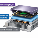
- Heat spreaders
- Thermal interface materials (TIMs)
- Lightweight heat sinks
- Battery thermal management
- Electronics cooling
This has led to the assumption that simply adding graphene or CNTs to a system will dramatically improve heat dissipation.
2. The Reality: Interface Dominates Performance
In practical systems, heat rarely travels through a perfect crystal.
Instead, it must pass through:
- Filler → matrix
- Coating → substrate
- Film → adhesive
- Particle → particle
These interfaces create thermal resistance, which often dominates overall performance.
Key reality check
A composite with graphene or CNTs may have bulk conductivity of only 3–20 W/m·K, even though the filler itself is thousands.
Why?
- Poor dispersion
- Random orientation
- Weak contact between particles
- Polymer matrix limitations
- Contact resistance at interfaces
So while the intrinsic material is extraordinary, system-level gains depend heavily on engineering.
3. Graphene vs CNT in Thermal Systems
Graphene (plate-like structure)
Strengths
- Excellent in-plane heat spreading
- Good for thin films and coatings
- Works well in planar heat dissipation
- Useful in thermal interface layers
Challenges
- Hard to build vertical thermal pathways
- Requires alignment for best performance
- Layer stacking can increase resistance
Best use cases
- Heat spreader coatings
- Battery module surfaces
- Thermal films
- Hybrid TIM fillers
CNT (1D network structure)
Strengths
- Can form 3D conductive networks
- Better through-thickness pathways
- Effective at low loading for network formation
- Good for structural composites
Challenges
- Contact resistance between tubes
- Dispersion difficulty
- Cost vs benefit tradeoff
- Often improves mechanical more than thermal
Best use cases
- Structural thermal composites
- Encapsulation materials
- Hybrid filler systems
- EMI + thermal combined designs
4. Where Expectations Go Wrong
Myth 1: “Add 1% graphene → huge thermal boost”
Reality:
Below percolation threshold, improvement may be minimal.
Myth 2: “Higher loading always better”
Reality:
Too much filler increases viscosity, weakens structure, and raises cost.
Myth 3: “Material datasheet = system performance”
Reality:
Thermal interface design matters more than filler conductivity.
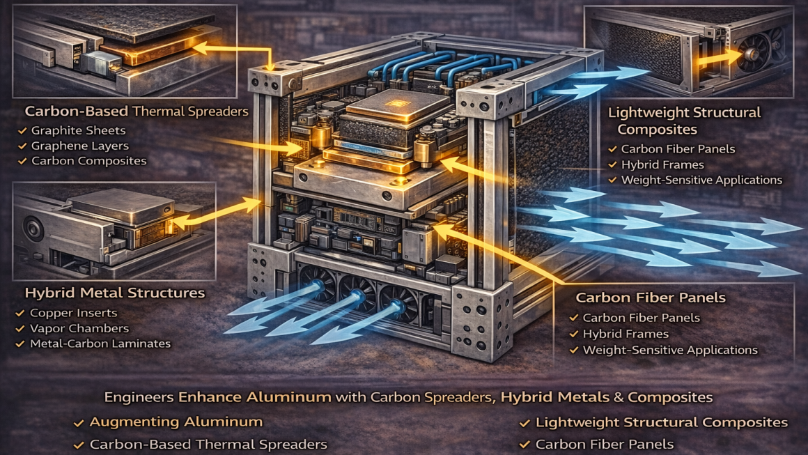
5. Where They Actually Work Well
Graphene and CNT deliver real value when used strategically:
✔ Thin coatings for heat spreading
- Electronics modules
- Battery packs
- LED systems
✔ Hybrid filler systems
Combining:
- Graphene + graphite
- CNT + ceramic fillers
- Carbon + metal particles
This often outperforms single-filler systems.
✔ Weight-sensitive applications
- Aerospace
- Portable electronics
- EV battery modules
Carbon materials offer thermal performance without heavy metal mass.
✔ Multi-function design
They can provide:
- Thermal conduction
- Electrical conductivity
- EMI shielding
- Structural reinforcement
This multifunctionality is often the real advantage.
6. Designing for Reality: Practical Guidelines
1. Start with system goal
Heat spreading? Interface reduction? Weight savings?
2. Focus on interfaces
Improve contact before chasing higher conductivity.
3. Use hybrid structures
Carbon materials work best with metals or ceramics.
4. Optimize loading
More is not always better.
5. Test in real geometry
Lab conductivity ≠ module performance.
7. The Bottom Line
Graphene and CNT are not “drop-in replacements” for copper or aluminum.
They are engineering tools that work best when integrated thoughtfully into system design.
Concept level:
Extraordinary thermal conductivity.
Reality:
Performance depends on dispersion, interfaces, and structure.
When used correctly, they enable:
- Lightweight thermal solutions
- Thin heat-spreading layers
- Multi-functional materials
- Next-generation electronics and battery designs
The real advantage isn’t just higher conductivity —
it’s design flexibility.